Ridgid R3202 Owners Manual - Page 11
Assembly
 |
View all Ridgid R3202 manuals
Add to My Manuals
Save this manual to your list of manuals |
Page 11 highlights
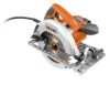
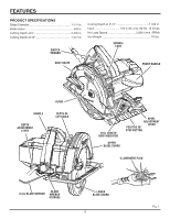
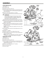
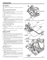
ASSEMBLY ATTACHING BLADE See Figures 2 - 3. Unplug the saw. Depress and hold spindle lock. Remove blade screw by turning it counterclockwise with the 6 mm blade wrench, while keeping the spindle lock button depressed. Remove outer blade washer ("D" washer). WARNING: If inner flange bushing has been removed, replace it before placing blade on spindle. Failure to do so will prevent blade from tightening properly and could result in serious personal injury. Retract the lower guard into the upper guard, making sure the lower guard spring works properly, allowing the guard to move freely. Check to see that the saw teeth and arrow on the saw blade and the arrow on the lower guard are pointing in the same direction. NOTE: The saw teeth point upward at the front of the saw as shown. Fit the saw blade inside the lower blade guard and onto the spindle. Replace "D" washer. Depress spindle lock and replace blade screw. Tighten blade screw securely by turning it clockwise with the 6 mm blade wrench. NOTE: Never use a blade that is too thick to allow the "D" washer to engage with the flats on the spindle. REMOVING BLADE See Figure 2 - 3. Unplug the saw. Depress and hold spindle lock. Remove blade screw by turning it counterclockwise with the provided 6 mm blade wrench, while keeping the spindle lock depressed. Remove outer blade washer ("D" washer). Lift lower blade guard. Remove blade. SPINDLE LOCK INNER FLANGE BUSHING BLADE SPINDLE OUTER BLADE WASHER BLADE SCREW ("D" WASHER) Fig. 2 SPINDLE LOCK TO TIGHTEN 6 mm BLADE TO WRENCH LOOSEN Fig. 3 11
-
 1
1 -
2
-
3
-
4
-
5
-
 6
6 -
 7
7 -
 8
8 -
 9
9 -
 10
10 -
 11
11 -
 12
12 -
 13
13 -
 14
14 -
 15
15 -
 16
16 -
17
-
18
-
19
-
20
-
21
-
22
 |
 |
