Ryobi AP1301 English Manual - Page 17
Adjustments - blade replacement
 |
View all Ryobi AP1301 manuals
Add to My Manuals
Save this manual to your list of manuals |
Page 17 highlights
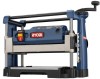
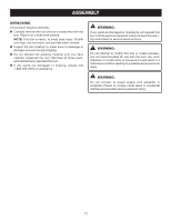
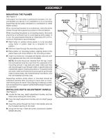
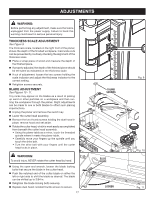
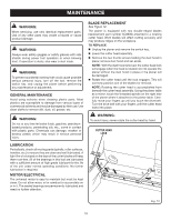
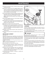
ADJUSTMENTS WARNING: Before performing any adjustment, make sure the tool is unplugged from the power supply. Failure to heed this warning could result in serious personal injury. THICKNESS SCALE ADJUSTMENT See Figure 9. The thickness scale, located on the right front of the planer, shows the depth of the finished workpiece. Inaccurate cuts can be prevented by routinely checking the alignment of the thickness scale. Plane a scrap piece of wood and measure the depth of the finished piece. If properly adjusted, the depth of the finished piece should be the same as indicated on the thickness scale. If out of adjustment, loosen the two screws holding the scale indicator and adjust the thickness indicator to the correct setting. Retighten screws securely. BLADE ADJUSTMENT See Figures 10 - 11. Tiny nicks may appear on the blades as a result of picking up sand or other particles on a workpiece and then running the workpiece through the planer. Slight adjustments can be made to one or both blades to offset such planing imperfections. Unplug the planer and remove the switch key. Lower the cutter head assembly. Remove the two thumb screws holding the dust hood in place; remove hood and set aside. Rotate the cutter head, which is most easily accomplished from beneath the cutter head assembly. • Using the planer table as a mirror, touch the threaded spindle where it meets the planer table. • Carefully move your fingers up the spindle until you touch the drive belt. • Turn the drive belt with your fingers until the cutter head locks in place. WARNING: To avoid injury, NEVER rotate the cutter head by hand. Using the open-end wrench, loosen the blade locking bolts that secure the blade in the cutter head. Push the notched end of the cutter blade on either the left or right side to shift the blade as desired. The blade can be shifted up to 3/64 in. Retighten the blade locking bolts securely. Replace dust hood; reinstall thumb screws to secure. 17 THUMB SCREWS SLIDE BLADE LOOSEN Fig. 9 Fig. 10 Fig. 11
-
 1
1 -
2
-
3
-
4
-
5
-
6
-
7
-
8
-
9
-
10
-
11
-
 12
12 -
 13
13 -
 14
14 -
 15
15 -
 16
16 -
 17
17 -
 18
18 -
 19
19 -
 20
20 -
 21
21 -
 22
22
 |
 |