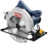
Ryobi CSB124 Operation Manual - Page 10
Assembly
 |
View all Ryobi CSB124 manuals
Add to My Manuals
Save this manual to your list of manuals |
Page 10 highlights
ASSEMBLY WARNING: Do not connect to power supply until assembly is complete. Failure to comply could result in accidental starting and possible serious personal injury. WARNING: A 7-1/4 in. blade is the maximum blade capacity of the saw. Also, never use a blade that is too thick to allow outer blade washer to engage with the flat on the spindle. Larger blades will come in contact with the blade guards, while thicker blades will prevent blade screw from securing blade on spindle. Either of these situations could result in a serious accident. NOTICE: To prevent damage to the spindle or spindle lock, always allow motor to come to a complete stop before engaging spindle lock. ATTACHING BLADE See Figures 2 - 4, pages 17 and 18. n Unplug the saw. n Depress and hold spindle lock button. n Remove blade screw by turning it counterclockwise with the blade wrench, while keeping the spindle lock button depressed. n Remove spring washer and outer blade washer ("D" washer). n Wipe a drop of oil onto the inner flange bushing and outer blade washer ("D" washer) where they contact blade. n Retract the lower blade guard into the upper blade guard using the lower blade guard handle. Make sure the lower guard spring works properly, allowing the guard to move freely. n Check to see that the saw teeth and arrow on the saw blade and the arrow on the upper guard are pointing in the same direction. NOTE: The saw teeth point upward at the front of the saw as shown. WARNING: If inner flange bushing has been removed, replace it before placing blade on spindle. Failure to do so will prevent blade from tightening properly and could result in serious personal injury. n Fit the saw blade inside the lower blade guard and onto the spindle. n Replace "D" washer. n Replace spring washer with cupped side against "D" washer. n Depress spindle lock button and replace blade screw. n Tighten blade screw securely by turning it clockwise with the blade wrench. NOTE: Never use a blade that is too thick to allow the "D" washer to engage with the flat on the spindle. REMOVING BLADE See Figures 2 - 4, pages 17 and 18. Unplug the saw. Depress and hold spindle lock button. Remove blade screw by turning it counterclockwise with the blade wrench, while keeping the spindle lock button depressed. Remove spring washer and outer blade washer ("D" washer). Lift lower blade guard. Remove blade. 10 - English
-
 1
1 -
2
-
3
-
4
-
 5
5 -
 6
6 -
 7
7 -
 8
8 -
 9
9 -
 10
10 -
 11
11 -
 12
12 -
 13
13 -
 14
14 -
 15
15 -
16
-
17
-
18
-
19
-
20
-
21
-
22
-
23
-
24
-
25
-
26
-
27
-
28
-
29
-
30
-
31
-
32
-
33
-
34
-
35
-
36
-
37
-
38
-
39
-
40
-
41
-
42
-
43
-
44
-
45
-
46
-
47
-
48
-
49
-
50
-
51
-
52
 |
 |
