Ryobi DP121L English Manual - Page 16
Installing/changing Worklight Bulb, Mounting The Drill Press - 12 drill press
 |
View all Ryobi DP121L manuals
Add to My Manuals
Save this manual to your list of manuals |
Page 16 highlights
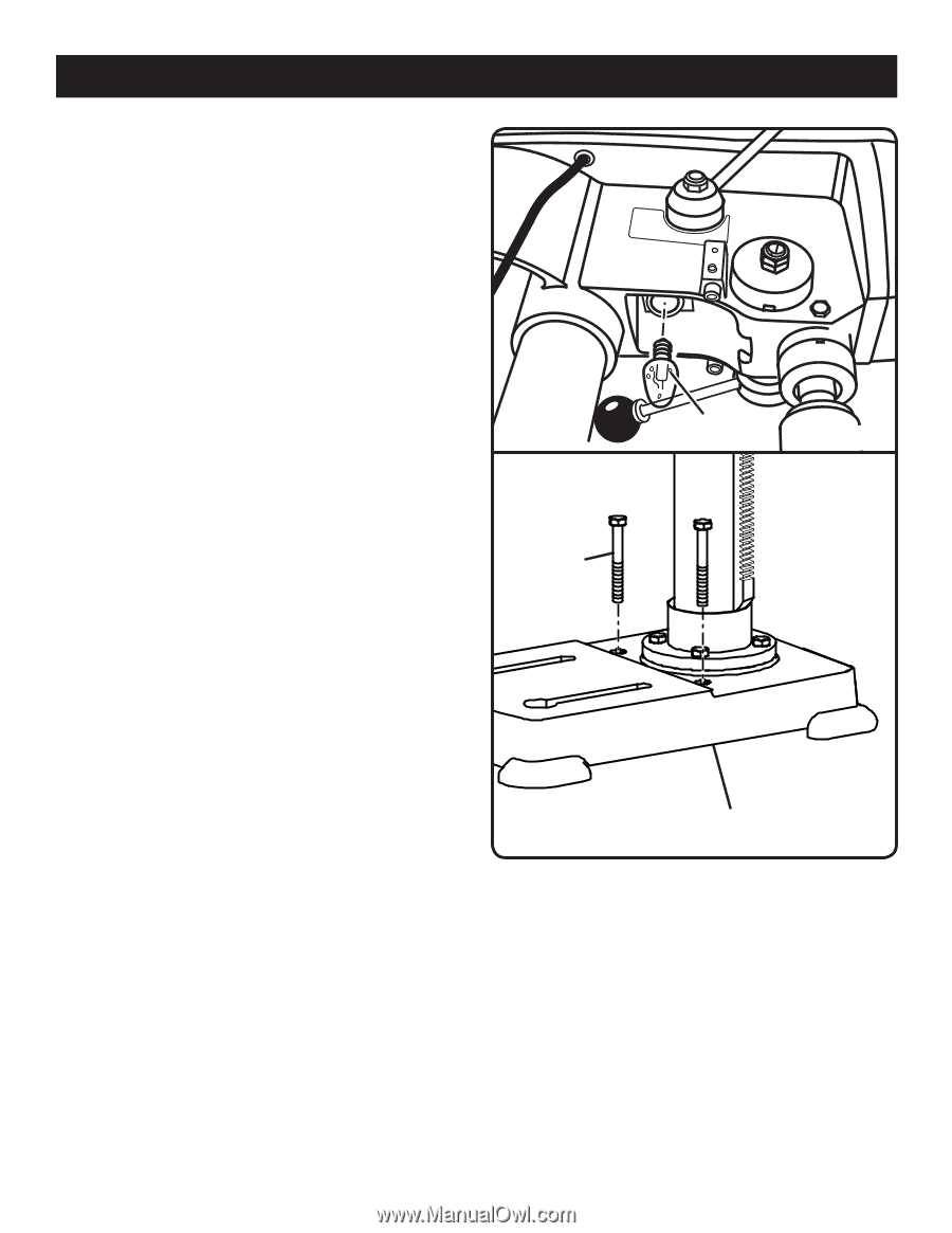
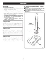
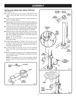
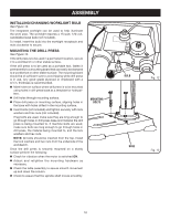
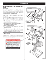
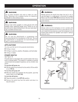
assembly Installing/changing worklight bulb See Figure 12. The integrated worklight can be used to help illuminate the work area. The worklight requires a 15-watt, 120-volt, candelabra-base bulb (not included). To install, insert the bulb into the worklight receptacle and twist clockwise to secure. Mounting the Drill press See Figure 13. If the drill press is to be used in a permanent location, secure it to a workbench or other stable surface. If the drill press is to be used as a portable tool, fasten it permanently to a mounting board that can easily be clamped to a workbench or other stable surface. The mounting board should be of sufficient size to avoid tipping while drill press is in use. Any good grade plywood or chipboard with a 3/4 in. thickness is recommended. ■ Mark holes on surface where drill press is to be mounted using holes in drill press base as a template for hole pattern. ■ Drill holes through mounting surface. ■ Place drill press on mounting surface, aligning holes in the base with holes drilled in the mounting surface. ■ Insert bolts (not included) and tighten securely with lock washers and hex nuts (not included). If lag bolts are used, make sure they are long enough to go through holes in drill press base and material the drill press is being mounted to. If machine bolts are used, make sure bolts are long enough to go through holes in drill press, the material being mounted to, and the lock washers and hex nuts. Note: All bolts should be inserted from the top. Install the lock washers and hex nuts from the underside of the workbench. Once the drill press is securely mounted on a sturdy surface perform the following: Check for vibration when the motor is switched ON. Adjust and retighten the mounting hardware as necessary. Check the table assembly to assure smooth movement up and down the column. Check to assure that the spindle shaft moves s moothly. mounting bolts bulb Fig. 12 base Fig. 13 16
-
 1
1 -
2
-
3
-
4
-
5
-
6
-
7
-
8
-
9
-
10
-
 11
11 -
 12
12 -
 13
13 -
 14
14 -
 15
15 -
 16
16 -
 17
17 -
 18
18 -
 19
19 -
 20
20 -
 21
21 -
22
-
23
-
24
 |
 |