Ryobi RTS21 English Manual - Page 24
Warning, To Set The Rip Fence Scale Indicator, To The Blade, To Use The Rip Fence, To Use The Miter
 |
View all Ryobi RTS21 manuals
Add to My Manuals
Save this manual to your list of manuals |
Page 24 highlights
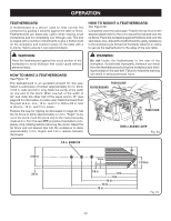
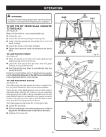
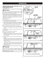
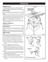
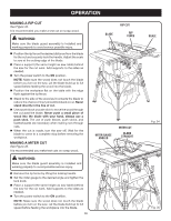
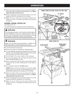
operation WARNING: To reduce the risk of injury, always make sure the rip fence is parallel to the blade before beginning any operation. To Set the rip fence Scale indicator to the Blade See Figure 24. Begin with the blade at a zero angle (straight up). Unplug the saw. Loosen the rip fence by lifting the locking lever. Using a framing square, set the rip fence 2 in. from the blade tip edge. Loosen the screw on the scale indicator. Tighten the screw and check the dimension and the rip fence. TO use the Rip Fence See Figure 25. Place the rear lip on the rear of the saw table and pull slightly toward the front of the unit. Lower the front end of the rip fence onto the guide surfaces on top of the front rail. Push the locking lever down to automatically align and secure the fence. Check for a smooth gliding action. If adjustments are needed, see To Check the Alignment of the Rip Fence to the Blade in the Adjustment section of this manual. TO use the miter gauge See Figure 26. The miter gauge provides greater accuracy in angled cuts. For very close tolerances, test cuts are recommended. There are two miter gauge grooves, one on either side of the blade. When making a 90° cross cut, you can use either miter gauge groove. When making a beveled cross cut (the blade tilted in relation to the table) the miter gauge should be located in the groove on the right so that the blade is tilted away from the miter gauge and your hands. The miter gauge can be turned 60° to the right or left. Loosen the lock knob. With the miter gauge in the miter gauge groove, rotate the gauge until the desired angle is reached on the scale. Retighten the lock knob. Blade Rip fence Scale 2 in. Scale indicator 2 in. mark SAW TABLE rip fence Front rail Locking lever Fig. 24 locking lever REAR LIP MITER GAUGE Fig. 25 LOCK KNOB Fig. 26 24
-
 1
1 -
2
-
3
-
4
-
5
-
6
-
7
-
8
-
9
-
10
-
11
-
12
-
13
-
14
-
15
-
16
-
17
-
18
-
 19
19 -
 20
20 -
 21
21 -
 22
22 -
 23
23 -
 24
24 -
 25
25 -
 26
26 -
 27
27 -
 28
28 -
 29
29 -
30
-
31
-
32
-
33
-
34
-
35
-
36
-
37
-
38
-
39
-
40
 |
 |
