Ryobi RY29550 Operator's Manual - Page 11
Assembly - accessories
 |
View all Ryobi RY29550 manuals
Add to My Manuals
Save this manual to your list of manuals |
Page 11 highlights
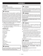
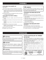
ASSEMBLY UNPACKING This product requires assembly. n Carefully remove the tool and any accessories from the box. Make sure that all items listed in the packing list are included. WARNING: This new product has been shipped in a partially assembled condition as described below. Carefully check the packing list below to ensure all items are included in the package; the packing list describes all loose items that are not assembled to the product as shipped. Do not operate the product if any packing list items are already assembled to your product when you unpack it. Call the customer service number below for assistance. Operation of a product that may have been improperly preassembled could result in serious personal injury. n Inspect the tool carefully to make sure no breakage or damage occurred during shipping. n Do not discard the packing material until you have carefully inspected and satisfactorily operated the tool. n If any parts are damaged or missing, please call 1-800-860-4050 for assistance. packing list Trimmer Assembly Pro Cut IITM String Head Spool Retainer Shoulder Strap 12 Volt Battery Charger Front Handle Wing Screw Wing Nut Bolt Washer Grass Deflector Bottle of 2-Cycle Lubricant Hanger Cap Operator's Manual WARNING: If any parts are damaged or missing do not operate this product until the parts are replaced. Failure to heed this warning could result in serious personal injury. WARNING: Do not attempt to modify this product or create accessories not recommended for use with this product. Use of this product with damaged or missing parts could result in serious personal injury. WARNING: To prevent accidental starting that could cause serious personal injury, always disconnect the engine spark plug wire from the spark plug and remove battery pack when assembling parts. installING THE POWER HEAD shaft TO THE ATTACHMENT See Figure 2. WARNING: Never install, remove, or adjust any attachment while power head is running. Failure to stop the engine can cause serious personal injury. The attachment connects to the power head shaft by means of a coupler device. Loosen the knob on the coupler of the power head shaft and remove the end cap from the attachment. Push in the button located on the attachment shaft. Align the button with the guide recess on the power head coupler and slide the two shafts together. Rotate the attachment shaft until the button locks into the positioning hole. NOTE: If the button does not release completely in the positioning hole, the shafts are not locked into place. Slightly rotate from side to side until the button is locked into place. Tighten the knob securely. WARNING: Be certain the knob is fully tightened before operating equipment; check it periodically for tightness during use to avoid serious personal injury. removing the attachment from the power head For removing or changing the attachment: Loosen the knob. Push in the button and twist the shafts to remove and separate ends. 7 - English
-
 1
1 -
2
-
3
-
4
-
5
-
 6
6 -
 7
7 -
 8
8 -
 9
9 -
 10
10 -
 11
11 -
 12
12 -
 13
13 -
 14
14 -
 15
15 -
 16
16 -
17
-
18
-
19
-
20
-
21
-
22
-
23
-
24
-
25
-
26
-
27
-
28
-
29
-
30
-
31
-
32
-
33
-
34
-
35
-
36
-
37
-
38
-
39
-
40
-
41
-
42
-
43
-
44
-
45
-
46
-
47
-
48
-
49
-
50
-
51
-
52
 |
 |