Ryobi RYSWP25 Operation Manual - Page 9
Assembly, Operation
 |
View all Ryobi RYSWP25 manuals
Add to My Manuals
Save this manual to your list of manuals |
Page 9 highlights
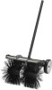
ASSEMBLY JOINING THE POWER HEAD TO THE SWEEPER ATTACHMENT See Figure 4. WARNING: Never attach or adjust any attachment while power head is running. Failure to stop the engine or motor could cause serious personal injury. The sweeper attachment connects to the power head by means of a coupler device. Stop the engine or motor and remove the spark plug wire, disconnect from the power supply, or remove the battery pack. Remove the hanger cap from the attachment. Loosen the knob on the coupler of the power head shaft. Push in the button located on the sweeper attachment. Align the button with the guide recess on the power head coupler and slide the two shafts together. Rotate attachment shaft until button locks into the positioning hole. NOTE: If the button does not release completely in the positioning hole, the shaft is not locked into place. Slightly rotate from side to side until the button is locked into place. Tighten the knob securely. WARNING: Be certain the knob is fully tightened before operating equipment. Check it periodically for tightness during use to avoid serious injury. REMOVING THE ATTACHMENT FROM THE POWER HEAD Stop the engine or motor and remove the spark plug wire, disconnect from the power supply, or remove the battery pack. Loosen the knob. Push in the button and twist the shafts to remove and separate ends. ATTACHING THE J-HANDLE See Figure 5. The J-handle must be used to ensure the best control and maximize operator safety when using the sweeper attachment. If the power head to which the sweeper attachment will be mounted does not have such a handle, install the handle provided. Place the bottom J-handle clamp on the drive shaft as shown. Insert the tab on the top J-handle clamp into the slot on the bottom J-handle clamp. Insert the end of the J-handle between the clamps so that holes align and handle will be located to the operator's left. Push the bolt through the clamp and handle. Install flat washer and wing nut to hold the assembly in place. Adjust the position of the handle. Tighten the wing nut securely. OPERATION WARNING: Do not allow familiarity with this product to make you careless. Remember that a careless fraction of a second is sufficient to inflict serious injury. WARNING: Always wear eye protection with side shields marked to comply with ANSI Z87.1 along with hearing and breathing protection. Failure to do so could result in objects being thrown into your eyes and other possible serious injuries. WARNING: Do not use any attachments or accessories not recommended by the manufacturer of this product. The use of attachments or accessories not recommended can result in serious personal injury. 7 - English
-
 1
1 -
2
-
3
-
 4
4 -
 5
5 -
 6
6 -
 7
7 -
 8
8 -
 9
9 -
 10
10 -
 11
11 -
 12
12 -
 13
13 -
 14
14 -
15
-
16
-
17
-
18
-
19
-
20
-
21
-
22
-
23
-
24
-
25
-
26
-
27
-
28
-
29
-
30
-
31
-
32
-
33
-
34
 |
 |
