Samsung CLP 300 Service Manual - Page 23
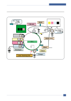
Developed Image on OPC is transferred onto ITB by T1 Process, Exposing, Developing, Transfer 1 - itb unit
 |
UPC - 635753721041
View all Samsung CLP 300 manuals
Add to My Manuals
Save this manual to your list of manuals |
Page 23 highlights
System Overview Exposing One polygon motor ( 6 facet ) Single beam LD (1ea) LD wavelength : 785nm Polygon motor rpm : 23747.5 LSU energy : 0.25uJ/cm^2 OPC exposed potential : -50V 1. Exposing is implemented by laser striking on to OPC with uniform potential 2. Laser beam is modulated according to image to be printed that is from PC 3. Latent Image is formed on OPC, which is developed with toner Developing Non-magnetic, mono component Non-contact development Developing bias : DC + AC AC peak to peak : 1.5 ~ 2.0kV Mass on developing roller : 550 ~ 600ug/cm^2 Toner coulomb : 15 ~ 20uC/g Roller diameter : 10mm Roller resistivity : 10^5 ~ 10^6 ohm-cm Process speed ratio : 1.2 (OPC=1.0) Color order : Y -> M -> C -> K 1. Only latent image formed by exposing process is developed with toner 2. AC + DC Voltage is being used to develop toner into latent image on OPC because non-contact developing method is adopted 3. Y, M, C, and K Images are sequentially developed onto OPC and transferred onto Intermediate Transfer Belt (hereafter ITB) to form a color image on ITB 4. Toner Bottles are used to supply toner into developer compartment 5. Toner level is being sensed to control toner supply from toner bottle to developer Transfer 1 Multi-pass transfer Indirect transfer Transfer voltage : 0.5 ~ 2.0kV (controllable) Roller diameter : 14mm Roller resistivity : ~ 10^7 ohm-cm Belt resistivity : 10^9 ~ 10^11 ohm-cm Environment sensing by Y-transfer roller Transfer unit life : 50K images 1. Developed Image on OPC is transferred onto ITB by T1 Process 2. T1 Voltage is positive which attract toner to ITB 3. 4 times of T1 process is required to make a color image on ITB, which means multi-pass process 4. ITB has a hole as a fiducial mark for timing. Engine control for color image is synchronous with it, ITB Home Sensing Signal Samsung Electronics Service Manual 3-5
-
 1
1 -
2
-
3
-
4
-
5
-
6
-
7
-
8
-
9
-
10
-
11
-
12
-
13
-
14
-
15
-
16
-
17
-
 18
18 -
 19
19 -
 20
20 -
 21
21 -
 22
22 -
 23
23 -
 24
24 -
 25
25 -
 26
26 -
 27
27 -
 28
28 -
29
-
30
-
31
-
32
-
33
-
34
-
35
-
36
-
37
-
38
-
39
-
40
-
41
-
42
-
43
-
44
-
45
-
46
-
47
-
48
-
49
-
50
-
51
-
52
-
53
-
54
-
55
-
56
-
57
-
58
-
59
-
60
-
61
-
62
-
63
-
64
-
65
-
66
-
67
-
68
-
69
-
70
-
71
-
72
-
73
-
74
-
75
-
76
-
77
-
78
-
79
-
80
-
81
-
82
-
83
-
84
-
85
-
86
-
87
-
88
-
89
-
90
-
91
-
92
-
93
-
94
-
95
-
96
-
97
-
98
-
99
-
100
-
101
-
102
-
103
-
104
-
105
-
106
-
107
-
108
-
109
-
110
-
111
-
112
-
113
-
114
-
115
-
116
-
117
-
118
-
119
-
120
-
121
-
122
-
123
-
124
-
125
-
126
-
127
-
128
-
129
-
130
-
131
-
132
-
133
-
134
-
135
-
136
-
137
-
138
-
139
-
140
-
141
-
142
-
143
-
144
-
145
-
146
-
147
-
148
-
149
-
150
-
151
-
152
-
153
-
154
-
155
-
156
-
157
-
158
-
159
 |
 |
