Samsung LN-R377D Quick Guide (easy Manual) (ver.1.0) (English) - Page 9
Rear Panel Jacks
 |
View all Samsung LN-R377D manuals
Add to My Manuals
Save this manual to your list of manuals |
Page 9 highlights
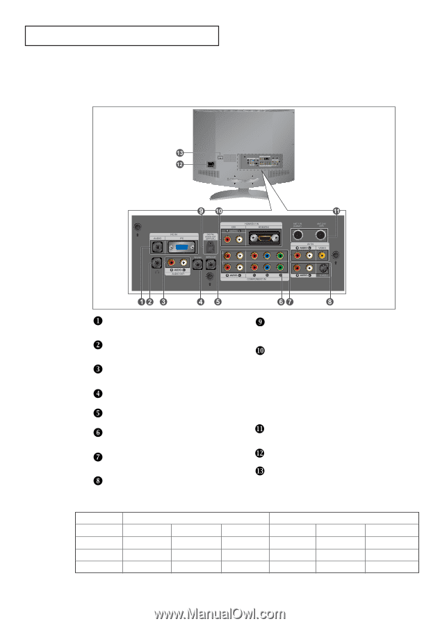
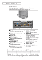
G E N E R A L I N F O R M AT I O N Rear Panel Jacks Use the rear panel jacks to connect an A/V component that will be connected continuously, such as a VCR or a DVD player. For more information on connecting equipment, see pages 7-16. PC IN Connect to the video and audio output jacks on your PC. HEADPHONE JACK Connect a set of external headphones for private listening. AUDIO OUT Connect to the audio input jacks on your Amplifier/Home theater. Anynet OUTPUT Refer to "Anynet AV Owner's Instructions". SERVICE Connector for service only. COMPONENT IN Connect component video/audio from a DVD/Set-Top Box. AV IN Video and audio inputs for external devices, such as a camcorder or VCR. S-VIDEO IN Video inputs for external devices with an S-Video output, such as a camcorder or VCR. DIGITAL AUDIO OUT (OPTICAL) Connect to a Digital Audio component. HDMI/DVI IN Connect to the HDMI jack of a device with an HDMI output. Use the HDMI/DVI terminal for DVI connection to an external device. You should use the DVI to HDMI cable or DVI-HDMI Adapter (DVI to HDMI) for the connection, and the 'R -AUDIO -L' terminal on DVI-IN for sound output. - HDMI/DVI IN terminal does not support PC. - No sound connection is needed for an HDMI to HDMI connection. ANT IN Connect to an antenna or to a cable TV system. (See pages 7~10, 55) POWER INPUT Connect the supplied power cord. KENSINGTON LOCK Refer to "Using the Anti-Theft Kensington Lock" on page 106. Speaker Audio Out RF AV, S-Video Component, PC, HDMI RF AV, S-VIDEO Component, PC, HDMI Internal Mute Off Speaker Output Speaker Output Speaker Output Sound Output Sound Output Sound Output Internal Mute On Mute Mute Mute Sound Output Sound Output Sound Output Video No Signal Mute Mute Mute Mute Sound Output Sound Output When "Internal mute" is set to "On", Sound menus except "Multi-Track Options" and "Digital Output" cannot be adjusted. English-3
-
 1
1 -
2
-
3
-
 4
4 -
 5
5 -
 6
6 -
 7
7 -
 8
8 -
 9
9 -
 10
10 -
 11
11 -
 12
12 -
 13
13 -
 14
14 -
15
-
16
-
17
-
18
-
19
-
20
-
21
-
22
-
23
-
24
-
25
-
26
-
27
-
28
-
29
-
30
-
31
-
32
-
33
-
34
-
35
-
36
-
37
-
38
-
39
-
40
-
41
-
42
-
43
-
44
-
45
-
46
-
47
-
48
-
49
-
50
-
51
-
52
-
53
-
54
-
55
-
56
-
57
-
58
-
59
-
60
-
61
-
62
-
63
-
64
-
65
-
66
-
67
-
68
-
69
-
70
-
71
-
72
-
73
-
74
-
75
-
76
-
77
-
78
-
79
-
80
-
81
-
82
-
83
-
84
-
85
-
86
-
87
-
88
-
89
-
90
-
91
-
92
-
93
-
94
-
95
-
96
-
97
-
98
-
99
-
100
-
101
-
102
-
103
-
104
-
105
-
106
-
107
-
108
-
109
-
110
-
111
-
112
-
113
-
114
 |
 |