Samsung SGH D900i Service Manual - Page 18
Disassembly and Assembly Instructions, 3-1. Disassembly - red
 |
View all Samsung SGH D900i manuals
Add to My Manuals
Save this manual to your list of manuals |
Page 18 highlights
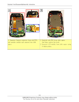
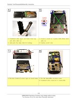
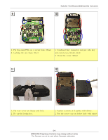
Exploded View/Disassembly&Assembly Instructions 5-3. Disassembly and Assembly Instructions 5-3-1. Disassembly 1 2 1. Remove 2 screw caps. 2. Loosen a screw this six point form Rear. 1. Make the space between rear cover and front cover using assembly stick. 2. And then widen space with hand and separate 2 parts. 3 4 1. Remove 2 keys. (Red) 2. Open 2 covers. (Blue) 3. Open the Key connector. (Violet) 1. Upside down the main PBA with moving slide. Be careful the hook. (Red) 2. Open the LCD connector. (Blue) 5-4 SAMSUNG Proprietary-Contents may change without notice This Document can not be used without Samsung's authorization
-
 1
1 -
2
-
3
-
4
-
5
-
6
-
7
-
8
-
9
-
10
-
11
-
12
-
 13
13 -
 14
14 -
 15
15 -
 16
16 -
 17
17 -
 18
18 -
 19
19 -
 20
20 -
 21
21 -
 22
22 -
 23
23 -
24
-
25
-
26
-
27
-
28
-
29
-
30
-
31
-
32
-
33
-
34
-
35
-
36
-
37
-
38
-
39
-
40
-
41
-
42
-
43
-
44
-
45
-
46
-
47
-
48
-
49
-
50
-
51
-
52
-
53
-
54
-
55
-
56
-
57
-
58
-
59
-
60
-
61
-
62
-
63
-
64
-
65
-
66
-
67
-
68
-
69
 |
 |

SAMSUNG Proprietary-Contents may change without notice
Exploded View/Disassembly&Assembly Instructions
5-4
This Document can not be used without Samsung's authorization
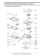
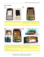
5-3. Disassembly and Assembly Instructions
5-3-1. Disassembly
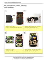
1. Remove 2 screw caps.
2. Loosen a screw this six point form Rear.
1. Make the space between rear cover and
front cover using assembly stick.
2. And then widen space with hand and
separate 2 parts.
1. Remove 2 keys. (Red)
2. Open 2 covers. (Blue)
3. Open the Key connector. (Violet)
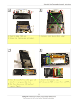
1. Upside down the main PBA with moving
slide. Be careful the hook. (Red)
2. Open the LCD connector. (Blue)
1
2
3
4