Sanyo PLV 80 Owners Manual - Page 57
Configurations Of Terminals, Appendix, Computer Input-1 Terminals Analog, Control Port Connector
 |
UPC - 086483059254
View all Sanyo PLV 80 manuals
Add to My Manuals
Save this manual to your list of manuals |
Page 57 highlights
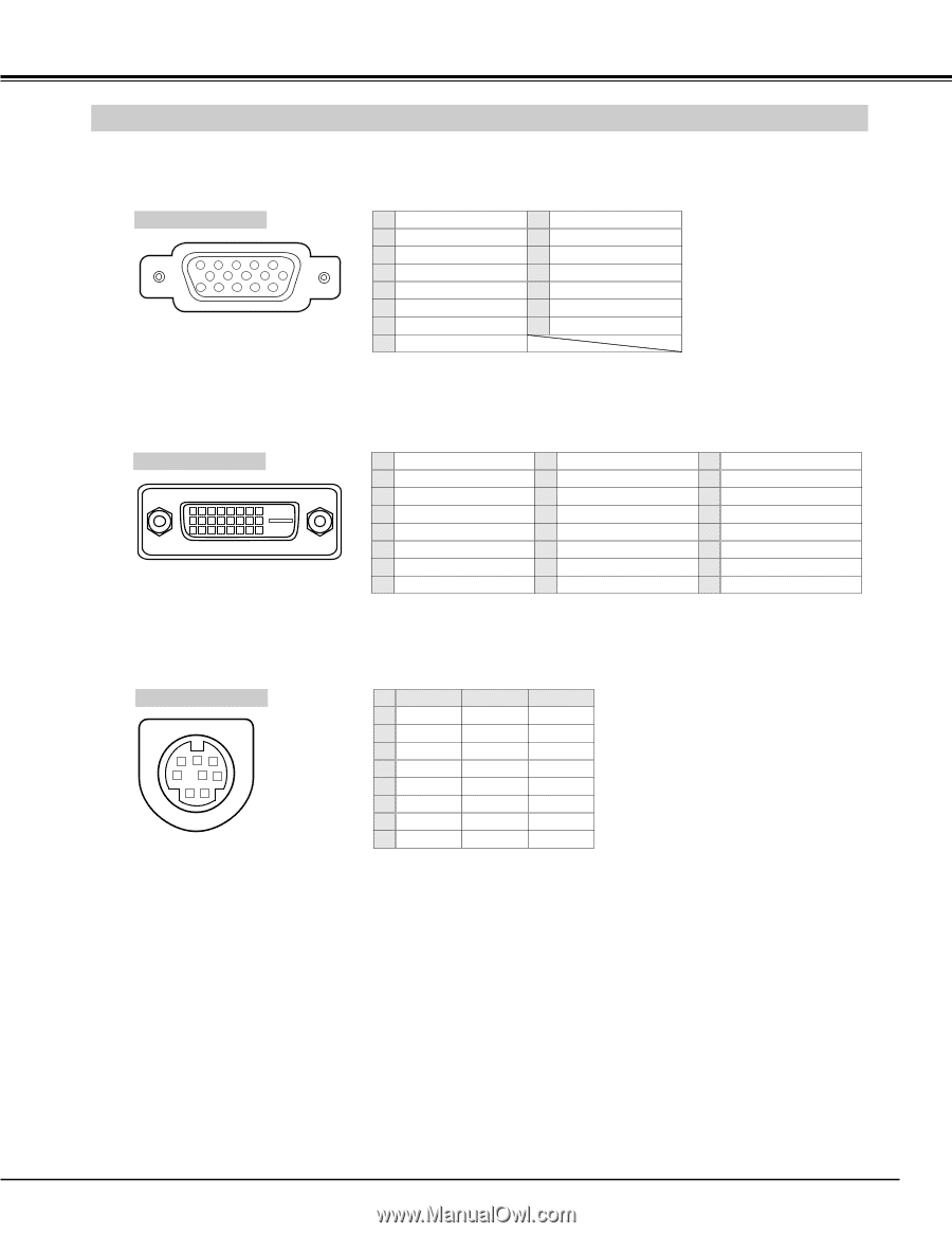
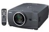
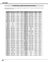
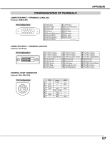
CONFIGURATIONS OF TERMINALS COMPUTER INPUT-1 TERMINALS (ANALOG) Terminal : HDB15-PIN Pin Configuration 54 32 1 10 9 8 7 6 15 14 13 12 11 1 Red Input 9 +5V Power 2 Green Input 10 Ground (Vert.sync.) 3 Blue Input 11 Sense 0 4 Sense 2 12 DDC Data 5 Ground (Horiz.sync.) 13 Horiz. sync. 6 Ground (Red) 14 Vert. sync. 7 Ground (Green) 15 DDC Clock 8 Ground (Blue) APPENDIX COMPUTER INPUT-1 TERMINAL (DIGITAL) Terminal : DVI 24-pin Pin Configuration 12345678 9 10 11 12 13 14 15 16 17 18 19 20 21 22 23 24 1 T.M.D.S. Data2- 9 T.M.D.S. Data1- 17 T.M.D.S. Data0- 2 T.M.D.S. Data2+ 10 T.M.D.S. Data1+ 18 T.M.D.S. Data0+ 3 T.M.D.S. Data2 Shield 11 T.M.D.S. Data1 Shield 19 T.M.D.S. Data0 Shield 4 No Connect 12 No Connect 20 No Connect 5 No Connect 13 No Connect 21 No Connect 6 DDC Clock 14 +5V Power 22 T.M.D.S. Clock Shield 7 DDC Data 15 Ground (for +5V) 23 T.M.D.S. Clock+ 8 No Connect 16 Hot Plug Detect 24 T.M.D.S. Clock- CONTROL PORT CONNECTOR Terminal : Mini DIN 8-PIN Pin Configuration 876 5 43 21 PS/2 Serial ADB 1 ----- R X D ----- 2 CLK ----- ADB 3 DATA ----- ----- 4 GND GND GND 5 ----- RTS / CTS ----- 6 ----- T X D ----- 7 GND GND ----- 8 ----- GND GND 57
-
 1
1 -
2
-
3
-
4
-
5
-
6
-
7
-
8
-
9
-
10
-
11
-
12
-
13
-
14
-
15
-
16
-
17
-
18
-
19
-
20
-
21
-
22
-
23
-
24
-
25
-
26
-
27
-
28
-
29
-
30
-
31
-
32
-
33
-
34
-
35
-
36
-
37
-
38
-
39
-
40
-
41
-
42
-
43
-
44
-
45
-
46
-
47
-
48
-
49
-
50
-
51
-
 52
52 -
 53
53 -
 54
54 -
 55
55 -
 56
56 -
 57
57 -
 58
58 -
 59
59 -
 60
60
 |
 |