Sanyo VCC-ZM600N Installation Manual - Page 4
Parts Names and Functions
 |
View all Sanyo VCC-ZM600N manuals
Add to My Manuals
Save this manual to your list of manuals |
Page 4 highlights
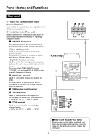
Parts Names and Functions Rear panel 1 VIDEO OUT connector (BNC type) Outputs video signal. Connect this terminal to the video input terminal of the external device. 2 Control terminals (Push-lock) Used to perform the control functions such as controlling the camera remotely or inputting/ outputting alarm. 1 ALARM IN 1/2 terminal These terminals can be used as an input terminal for either of the following functions. Used to connect the alarm device that detects intruders. Connect this terminal to an external alarm switch or an infrared sensor, etc. Used to switch the viewing mode manually between the color mode and the black/white mode. To do so, select [DAY/NIGHT], choose "COLOR", and set the [EXT ALARM] to the desired alarm input channel. 2 ALARM OUT terminal Used to connect to an external buzzer or lamp. When an alarm is detected, the device connected to the terminal notifies that an alarm is detected. 3 COM terminal (earth terminal) 4 FOCUS terminal Used to perform the focus adjustment remotely by connecting an external switch. • DC ± (6 - 12 V), +: FAR, -: NEAR 5 ZOOM terminal Used to zoom in/out by connecting an external switch. • DC ± (6 - 12 V), +: WIDE, -: TELE 123 A B COM RS485 UTP 3 POWER lamp 1 2 ALARM IN 1 ALARM OUT FOCUS POWER VIDEO OUT A B COM RS485 UTP ALARM IN 2 AC24V GND DC12V 4 COM ZOOM ALARM IN 2 1 2 3 4 5 ALARM IN 1 ALARM OUT FOCUS COM ZOOM b How to use the push-lock switch When connecting the cable, press and hold down the protrusion of the terminal, insert the cable into the terminal, and then release the protrusion. 3
-
 1
1 -
 2
2 -
 3
3 -
 4
4 -
 5
5 -
 6
6 -
 7
7 -
 8
8 -
 9
9 -
 10
10 -
11
-
12
-
13
-
14
-
15
-
16
-
17
-
18
-
19
-
20
-
21
-
22
-
23
-
24
-
25
-
26
-
27
-
28
-
29
-
30
-
31
-
32
-
33
-
34
-
35
-
36
-
37
-
38
-
39
-
40
-
41
-
42
-
43
-
44
-
45
-
46
-
47
-
48
-
49
-
50
-
51
-
52
-
53
-
54
-
55
-
56
 |
 |
