Sanyo VDC-HD3300 VDC-HD3300 Manual - Page 7
Introduction 7/15 - mount
 |
UPC - 086483075087
View all Sanyo VDC-HD3300 manuals
Add to My Manuals
Save this manual to your list of manuals |
Page 7 highlights
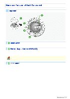
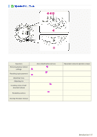
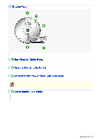
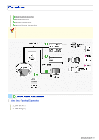
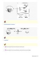
For the detailed procedures for connecting terminals and cables, refer to the "Connections" section. Use these coupling holes to mount the camera to the separately-sold base bracket. Use this socket to connect the camera to your PC to enable network operation. Use this cable to connect a 24 VAC or 12 VDC power supply. There is no power indicator on the camera. Alarm input cable: Connect an external switch, infrared sensor, or other device to detect alarm conditions such as the entry of an intruder. Alarm output cable: Connect a buzzer, lamp, or other alarm device. Introduction 7/15
-
 1
1 -
 2
2 -
 3
3 -
 4
4 -
 5
5 -
 6
6 -
 7
7 -
 8
8 -
 9
9 -
 10
10 -
 11
11 -
 12
12 -
13
-
14
-
15
-
16
-
17
-
18
-
19
-
20
-
21
-
22
-
23
-
24
-
25
-
26
-
27
-
28
-
29
-
30
-
31
-
32
-
33
-
34
-
35
-
36
-
37
-
38
-
39
-
40
-
41
-
42
-
43
-
44
-
45
-
46
-
47
-
48
-
49
-
50
-
51
-
52
-
53
-
54
-
55
-
56
-
57
-
58
-
59
-
60
-
61
-
62
-
63
-
64
-
65
-
66
-
67
-
68
-
69
-
70
-
71
-
72
-
73
-
74
-
75
-
76
-
77
-
78
-
79
-
80
-
81
-
82
-
83
-
84
-
85
-
86
-
87
-
88
-
89
-
90
-
91
-
92
-
93
-
94
-
95
-
96
-
97
-
98
-
99
-
100
-
101
-
102
-
103
-
104
-
105
-
106
-
107
-
108
-
109
-
110
-
111
-
112
-
113
-
114
-
115
-
116
 |
 |

For the detailed procedures for connecting terminals and cables, refer to the “Connections” section.
Use these coupling holes to mount the camera to the separately-sold base bracket.
Use this socket to connect the camera to your PC to enable network operation.
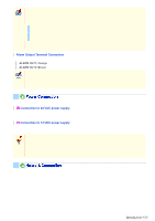
Use this cable to connect a 24 VAC or 12 VDC power supply.
There is no power indicator on the camera.
Alarm input cable: Connect an external switch, infrared sensor, or other device to detect alarm conditions
such as the entry of an intruder.
Alarm output cable: Connect a buzzer, lamp, or other alarm device.
Introduction 7/15