Seagate ST1000VX000 SV35 Series PATA Product Manual - Page 50
Error Outputs, ERROR REGISTER FIELD DESCRIPTIONS, ICRC Interface CRC Error, UNC Uncorrectable, CCTO
 |
View all Seagate ST1000VX000 manuals
Add to My Manuals
Save this manual to your list of manuals |
Page 50 highlights
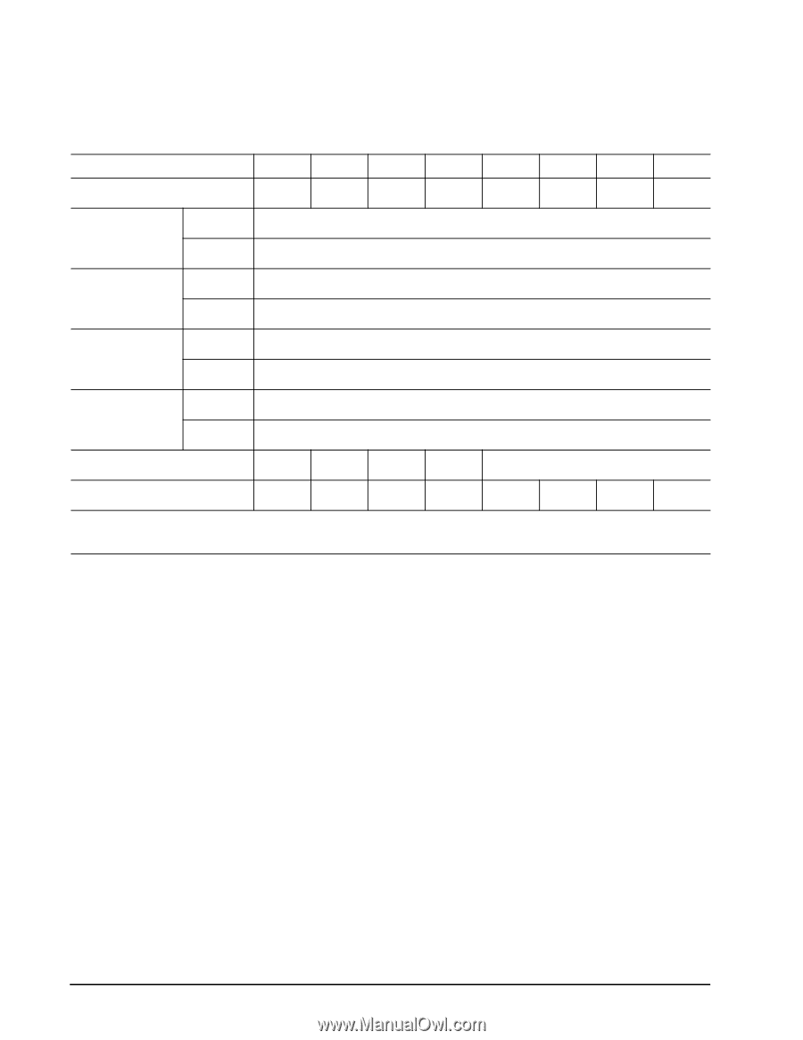
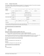
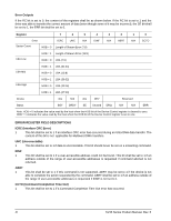
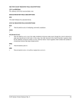
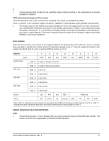
Error Outputs If the RC bit is set to 0, the content of the registers shall be as shown below. If the RC bit is set to 1 and the drive was able to transfer the correct amount of data (even though some of it may be incorrect), the SE bit shall be set to 1, the ERR bit shall be set to 0. Register 7 6 5 4 3 2 1 0 Error ICRC UNC N/A IDNF N/A ABRT N/A CCTO Sector Count HOB = 0 Length of Stream Error (7:0) LBA Low HOB = 1 Length of Stream Error (15:8) HOB = 0 LBA (7:0) LBA Mid HOB = 1 LBA (31:24) HOB = 0 LBA (15:8) LBA High HOB = 1 LBA (39:32) HOB = 0 LBA (23:16) HOB = 1 LBA (47:40) Device obs N/A obs DEV Reserved Status BSY DRDY SE Unused DRQ N/A N/A ERR Note: HOB = 0 indicates the value read by the host when the HOB bit of the Device Control register is cleared to zero. HOB = 1 indicates the value read by the host when the HOB bit of the Device Control register is set to one. ERROR REGISTER FIELD DESCRIPTIONS ICRC (Interface CRC Error) 1 This bit shall be set to 1 if an interface CRC error has occurred during an Ultra DMA data transfer. The content of this bit is not applicable for Multiword DMA transfers. UNC (Uncorrectable) 1 This bit shall be set to 1 if data is uncorrectable. This bit should never be set on a streaming command. IDNF 1 This bit shall be set to 1 if a user-accessible address could not be found. This bit shall be set to 1 if an address outside of the range of user-accessible addresses is requested if command aborted is not returned. ABRT 1 This bit shall be set to 1 if this command is not supported. ABRT may be set to 1 if the device is not able to complete the action requested by the command. ABRT shall be set to 1 if an address outside of the range of user-accessible addresses is requested if IDNF is not set to 1. CCTO (Command Completion Time Out) 1 This bit shall be set to 1 if a Command Completion Time Out error has occurred. 44 SV35 Series Product Manual, Rev. B
-
 1
1 -
2
-
3
-
4
-
5
-
6
-
7
-
8
-
9
-
10
-
11
-
12
-
13
-
14
-
15
-
16
-
17
-
18
-
19
-
20
-
21
-
22
-
23
-
24
-
25
-
26
-
27
-
28
-
29
-
30
-
31
-
32
-
33
-
34
-
35
-
36
-
37
-
38
-
39
-
40
-
41
-
42
-
43
-
44
-
 45
45 -
 46
46 -
 47
47 -
 48
48 -
 49
49 -
 50
50 -
 51
51 -
 52
52 -
 53
53 -
 54
54 -
 55
55 -
56
-
57
-
58
-
59
-
60
-
61
-
62
-
63
-
64
 |
 |