Seagate ST1000VX000 SV35 Series PATA Product Manual - Page 53
ous CON STREAM command for this Stream type Read or Write. If the Default Command
 |
View all Seagate ST1000VX000 manuals
Add to My Manuals
Save this manual to your list of manuals |
Page 53 highlights
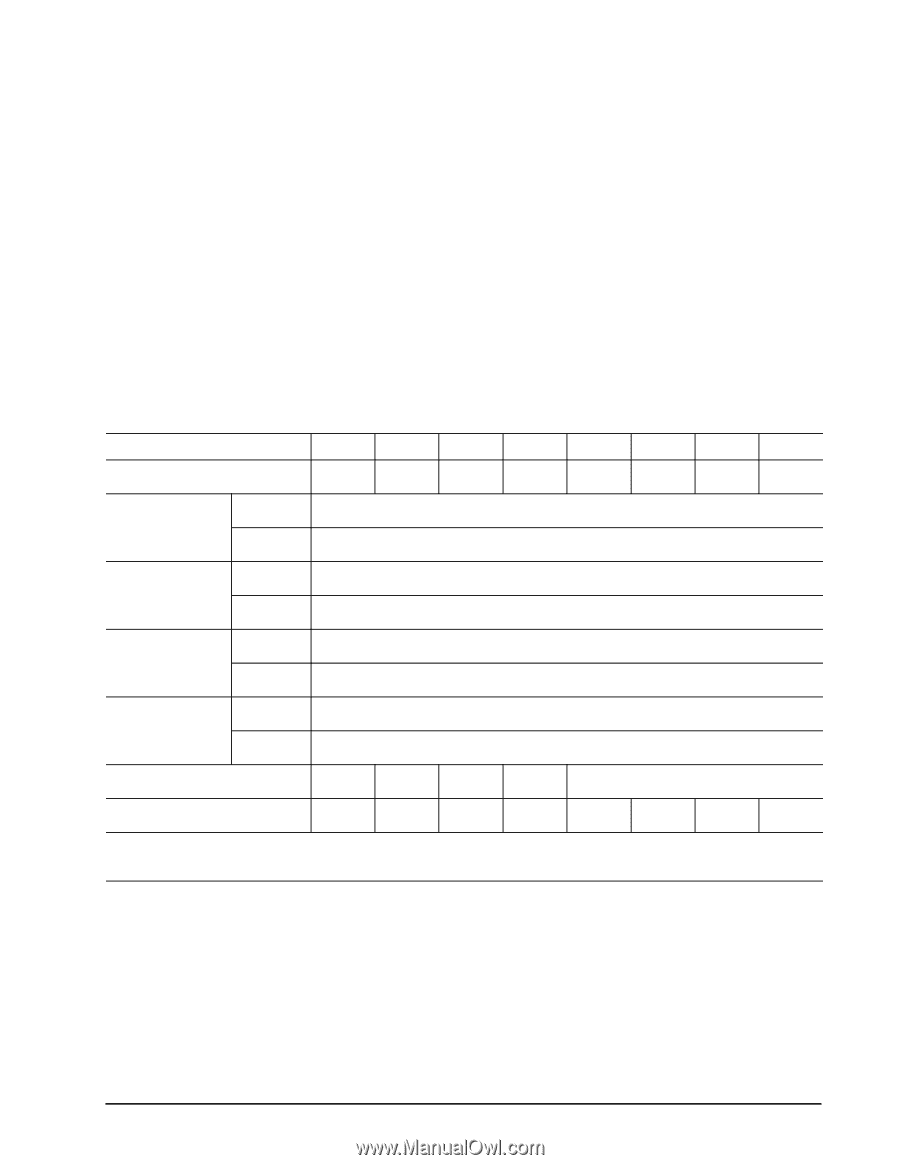
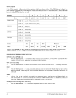
F 1 This bit specifies that all data for the specified stream shall be flushed to the media before command complete is reported. CCTL (Command Completion Time Limit) The time allowed for the current command to complete. This value is calculated as follows: CCTL = (content of the Features register Previous) * (IDENTIFY DEVICE data words (99:98)) microseconds 0 The device shall use the Default Command Completion Time Limit supplied with the most recent previ- ous CONFIGURE STREAM command for this Stream type (Read or Write). If the Default Command Completion Time Limit = 0, or no previous Configure Stream command was defined for this Stream ID, the result is vendor specific. The time is measured from the write of the command register to the final INTRQ for command completion. Error Outputs If the WC bit is set to 0, the content of the registers shall be as shown below. If the WC bit is set to 1 and the drive was able to transfer the correct amount of data (even though some of it may be written incorrectly to the media), the SE bit shall be set to 1 and the ERR bit shall be set to 0. Register 7 6 5 4 3 2 1 0 Error ICRC N/A N/A IDNF N/A ABRT N/A CCTO Sector Count HOB = 0 Length of Stream Error (7:0) LBA Low HOB = 1 Length of Stream Error (15:8) HOB = 0 LBA (7:0) LBA Mid HOB = 1 LBA (31:24) HOB = 0 LBA (15:8) LBA High HOB = 1 LBA (39:32) HOB = 0 LBA (23:16) HOB = 1 LBA (47:40) Device obs N/A obs DEV Reserved Status BSY DRDY SE Unused DRQ N/A N/A ERR Note: HOB = 0 indicates the value read by the host where the HOB bit of the Device Control register is set to 0. HOB = 1 indicates the value read by the host when the HOB bit of the Device Control register is set to 1. ERROR REGISTER FIELD DESCRIPTIONS ICRC 1 This bit shall be set to 1 if an interface CRC error has occurred during an Ultra DMA data transfer. The content of this bit is not applicable for Multiword DMA transfers. SV35 Series Product Manual, Rev. B 47
-
 1
1 -
2
-
3
-
4
-
5
-
6
-
7
-
8
-
9
-
10
-
11
-
12
-
13
-
14
-
15
-
16
-
17
-
18
-
19
-
20
-
21
-
22
-
23
-
24
-
25
-
26
-
27
-
28
-
29
-
30
-
31
-
32
-
33
-
34
-
35
-
36
-
37
-
38
-
39
-
40
-
41
-
42
-
43
-
44
-
45
-
46
-
47
-
 48
48 -
 49
49 -
 50
50 -
 51
51 -
 52
52 -
 53
53 -
 54
54 -
 55
55 -
 56
56 -
 57
57 -
 58
58 -
59
-
60
-
61
-
62
-
63
-
64
 |
 |