Seagate ST300MM0026 Savvio 10K.1 FC Product Manual - Page 19
Prefetch/multi-segmented cache control, Cache operation
 |
View all Seagate ST300MM0026 manuals
Add to My Manuals
Save this manual to your list of manuals |
Page 19 highlights
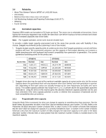
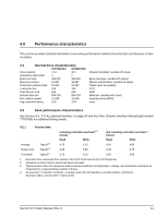
4.4 Prefetch/multi-segmented cache control The drive provides a prefetch (read look-ahead) and multi-segmented cache control algorithms that in many cases can enhance system performance. Cache refers to the drive buffer storage space when it is used in cache operations. To select this feature, the host sends the Mode Select command with the proper values in the applicable bytes in page 08h. Prefetch and cache operations are independent features from the standpoint that each is enabled and disabled independently using the Mode Select command; however, in actual operation, the prefetch feature overlaps cache operation somewhat as described in sections 4.5.1 and 4.5.2. All default cache and prefetch mode parameter values (Mode Page 08h) for standard OEM versions of this drive family are given in Table 17. 4.5 Cache operation Note. Refer to the Fibre Channel Interface Manual for more detail concerning the cache bits. Of the 8,192 Kbytes physical buffer space in the drive, approximately 7,100 Kbytes can be used as a cache. The buffer can be divided into logical segments (using Mode Select Page 08h, byte 13) from which data is read and to which data is written. The drive keeps track of the logical block addresses of the data stored in each segment of the buffer. If the cache is enabled (see RCD bit in the Fibre Channel Interface Manual ), data requested by the host with a read command is retrieved from the buffer, if possible, before any disc access is initiated. If cache operation is not enabled, the buffer (still segmented with the required number of segments) is still used, but only as circular buffer segments during disc medium read operations (disregarding Prefetch operation for the moment). That is, the drive does not check in the buffer segments for the requested read data, but goes directly to the medium to retrieve it. The retrieved data merely passes through some buffer segment on the way to the host. On a cache miss, all data transfers to the host are in accordance with buffer-full ratio rules. On a cache hit, the drive ignores the buffer-full ratio rules. See the explanation provided with the information about Mode Page 02h (disconnect/reconnect control) in the Fibre Channel Interface Manual. The following is a simplified description of the prefetch/cache operation: Case A-read command is received and the first logical block is already in the cache: 1. Drive transfers to the initiator the first logical block requested plus all subsequent contiguous logical blocks that are already in the cache. This data may be in multiple segments. 2. When a requested logical block is reached that is not in any cache segment, the drive fetches it and any remaining requested logical block addresses from the disc and puts them in a segment of the cache. The drive transfers the remaining requested logical blocks from the cache to the host in accordance with the Mode Select Disconnect/Reconnect parameters, page 02h. 3. If the prefetch feature is enabled, refer to section 4.5.2 for operation from this point. Case B-A Read command requests data, and the first logical block is not in any segment of the cache: 1. The drive fetches the requested logical blocks from the disc and transfers them into a segment, and then from there to the host in accordance with the Mode Select Disconnect/Reconnect parameters, page 02h. 2. If the prefetch feature is enabled, refer to section 4.5.2 for operation from this point. During a prefetch, the drive crosses a cylinder boundary to fetch data only if the Discontinuity (DISC) bit is set to 1 in bit 4 of byte 2 of the Mode Select parameters page 08h. Default is zero for bit 4. Each cache segment is actually a self-contained circular buffer whose length is an integer number of logical blocks. The wrap-around capability of the individual segments greatly enhances the cache's overall performance, allowing a wide range of user-selectable configurations. The drive supports operation of any integer number of segments from 1 to 32. Divide the 7,100 Kbytes in the buffer by the number of segments to get the segment size in bytes; then divide by the sector size to get the number of sectors per segment, any partial sectors remaining are not used. Default is 3 segments. Savvio FC Product Manual, Rev. D 13
-
 1
1 -
2
-
3
-
4
-
5
-
6
-
7
-
8
-
9
-
10
-
11
-
12
-
13
-
 14
14 -
 15
15 -
 16
16 -
 17
17 -
 18
18 -
 19
19 -
 20
20 -
 21
21 -
 22
22 -
 23
23 -
 24
24 -
25
-
26
-
27
-
28
-
29
-
30
-
31
-
32
-
33
-
34
-
35
-
36
-
37
-
38
-
39
-
40
-
41
-
42
-
43
-
44
-
45
-
46
-
47
-
48
-
49
-
50
-
51
-
52
-
53
-
54
-
55
-
56
-
57
-
58
-
59
-
60
-
61
-
62
-
63
-
64
-
65
-
66
-
67
-
68
-
69
-
70
-
71
-
72
-
73
-
74
-
75
-
76
-
77
-
78
-
79
-
80
-
81
-
82
-
83
-
84
 |
 |
