Seagate ST300MM0026 Savvio 10K.1 FC Product Manual - Page 74
Differential PECL output, Differential PECL input
 |
View all Seagate ST300MM0026 manuals
Add to My Manuals
Save this manual to your list of manuals |
Page 74 highlights
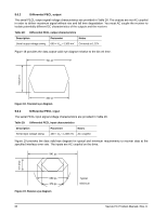
9.6.2 Differential PECL output The serial PECL output signal voltage characteristics are provided in Table 28. The outputs are not AC coupled in order to deliver maximum signal without rise and fall time degradation. You must AC couple the receiver to isolate potentially different DC characteristics of the outputs and the receiver. Table 28: Differential PECL output characteristics Description Parameter Notes Serial output voltage swing 600 < Vout < 1300 mV Centered at 1.32V Figure 18 provides the data output valid eye diagram relative to the bit cell time. 941 ps Vout (mv) 800 ps Figure 18. Transmit eye diagram 9.6.3 Differential PECL input The serial PECL input signal voltage characteristics are provided in Table 29. Table 29: Differential PECL input characteristics Description Parameter Notes Serial input voltage swing 200 < Vin < 1.300 mV AC coupled Figure 19 provides the data valid eye diagram for typical and minimum requirements to recover data at the specified interface error rate. The inputs are AC coupled on the drive. 941 ps Vin (mv) 659 ps 376 ps Figure 19. Receive eye diagram 68 Typical Minimum Savvio FC Product Manual, Rev. D
-
 1
1 -
2
-
3
-
4
-
5
-
6
-
7
-
8
-
9
-
10
-
11
-
12
-
13
-
14
-
15
-
16
-
17
-
18
-
19
-
20
-
21
-
22
-
23
-
24
-
25
-
26
-
27
-
28
-
29
-
30
-
31
-
32
-
33
-
34
-
35
-
36
-
37
-
38
-
39
-
40
-
41
-
42
-
43
-
44
-
45
-
46
-
47
-
48
-
49
-
50
-
51
-
52
-
53
-
54
-
55
-
56
-
57
-
58
-
59
-
60
-
61
-
62
-
63
-
64
-
65
-
66
-
67
-
68
-
 69
69 -
 70
70 -
 71
71 -
 72
72 -
 73
73 -
 74
74 -
 75
75 -
 76
76 -
 77
77 -
 78
78 -
 79
79 -
80
-
81
-
82
-
83
-
84
 |
 |
