Seagate ST300MM0026 Savvio 10K.1 FC Product Manual - Page 69
FC-AL transmitters and receivers, Power, Fault LED Out
 |
View all Seagate ST300MM0026 manuals
Add to My Manuals
Save this manual to your list of manuals |
Page 69 highlights
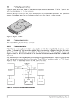
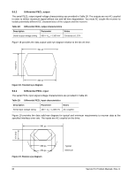
9.5.5 FC-AL transmitters and receivers A typical FC-AL differential copper transmitter and receiver pair is shown in Figure 17. The receiver is required to provide the AC coupling to eliminate ground shift noise. TX Transmitter 100 TY 100 Differential Transfer Medium .01 RX 100 Receiver RY .01 Figure 17. FC-AL transmitters and receivers Savvio drives use 100 ohm termination which makes it compatible with backplanes designed for 1, 2, or 4 Gbit Fibre Channel transfer rates. Previous generations of Seagate FC products used 150 ohm impedance for operation in host systems designed to operate in 1 or 2 Gbit transfer rate environments. 9.5.6 Power Power is supplied through the FC-SCA with support for +5 volts and +12 volts. All of the voltage pins in the drive connector are the same length. Four 12 volt pins provide +12 volt power to the drive. The current return for the +12 volt power supply is through the common ground pins. The supply current and return current must be distributed as evenly as possible among the pins. The maximum current typically occurs while the drive motor is starting. Three 5 volt pins provide logic power to the drive. The current return for the +5 volt power supply is through the common ground pins. Distribute supply and return current as evenly as possible among the voltage and ground pins. The mating connector pins use shorter contacts to achieve power surge reductions and to aid in "hot plugging" the drives. There are longer voltage contacts in the connector to enable the drive filter capacitors to charge. Current to the drive through the long charge pins is limited by the system in which the drive operates. Three of the +12 volt pins are shorter to allow capacitive pre-charging through the longer +12 volt charge pin. Two of the +5 volt pins are shorter to allow capacitive precharging through the longer +5 volt charge pin. 9.5.7 Fault LED Out The Fault LED Out signal is driven by the drive when: • the drive detects failure of both ports • the drive detects an internal failure • the drive receives the appropriate fault LED command from the host The Fault LED Out signal is designed to pull down the cathode of an LED. The anode is attached to the proper +5 volt supply through an appropriate current-limiting resistor. The LED and the current-limiting resistor are external to the drive. Savvio FC Product Manual, Rev. D 63
-
 1
1 -
2
-
3
-
4
-
5
-
6
-
7
-
8
-
9
-
10
-
11
-
12
-
13
-
14
-
15
-
16
-
17
-
18
-
19
-
20
-
21
-
22
-
23
-
24
-
25
-
26
-
27
-
28
-
29
-
30
-
31
-
32
-
33
-
34
-
35
-
36
-
37
-
38
-
39
-
40
-
41
-
42
-
43
-
44
-
45
-
46
-
47
-
48
-
49
-
50
-
51
-
52
-
53
-
54
-
55
-
56
-
57
-
58
-
59
-
60
-
61
-
62
-
63
-
 64
64 -
 65
65 -
 66
66 -
 67
67 -
 68
68 -
 69
69 -
 70
70 -
 71
71 -
 72
72 -
 73
73 -
 74
74 -
75
-
76
-
77
-
78
-
79
-
80
-
81
-
82
-
83
-
84
 |
 |
