Seagate ST300MM0026 Savvio 10K.1 SAS Product Manual - Page 75
other forms of compensation. A compliance interconnect is any physical interconnect with loss equal
 |
View all Seagate ST300MM0026 manuals
Add to My Manuals
Save this manual to your list of manuals |
Page 75 highlights
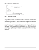
A combination of a zero-length test load and the transmitter compliance transfer function (TCTF) test load methodology is used for the specification of transmitter characteristics. This methodology specifies the transmitter signal at the test points on the required test loads. The transmitter uses the same settings (e.g., preemphasis, voltage swing) with both the zero-length test load and the TCTF test load. The signal specifications at IR are met under each of these loading conditions. The TCTF is the mathematical statement of the transfer function through which the transmitter shall be capable of producing acceptable signals as defined by a receive mask. The transmission magnitude response of the TCTF in dB is given by the following equation for 1.5 Gbps: S21 = -20 × log10(e) × ((6, 5 × 10⁻⁶ × f0, 5) + (2, 0 × 10-10 × f) + (3, 3 × 10-20 × f2)) dB for 50 MHz < f < 1.5 GHz, and: S21 = -5, 437dB for 1.5 GHz < f < 5.0 GHz, where: a) f is the signal frequency in hertz. The transmission magnitude response of the TCTF in dB is given by the following equation for 3.0 Gbps: S21 = -20 × log10(e) × ((6, 5 × 10⁻⁶ × f0, 5) + (2, 0 × 10-10 × f) + (3, 3 × 10-20 × f2)) dB for 50 MHz < f < 3.0 GHz, and: S21 = -10, 884dB for 3.0 GHz < f < 5.0 GHz, where: a) f is the signal frequency in hertz. The TCTF is used to specify the requirements on transmitters that may or may not incorporate pre-emphasis or other forms of compensation. A compliance interconnect is any physical interconnect with loss equal to or greater than that of the TCTF at the above frequencies that also meets the ISI loss requirements shown in figure 24 and figure 25. Compliance with the TCTF test load requirement is verified by measuring the signal produced by the transmitter through a physical compliance interconnect attached to the transmitter. Compliance with the zero-length test load requirement verified by measurement made across a load equivalent to the zero-length load shown in figure 23. For both test load cases, the transmitter delivers the output voltages and timing listed in table 28 at the designated compliance points. The default mask is IR for intra-cabinet TxRx connections. The eye masks are shown in 9.5.2.1. Savvio SAS Product Manual, Rev. D 69
-
 1
1 -
2
-
3
-
4
-
5
-
6
-
7
-
8
-
9
-
10
-
11
-
12
-
13
-
14
-
15
-
16
-
17
-
18
-
19
-
20
-
21
-
22
-
23
-
24
-
25
-
26
-
27
-
28
-
29
-
30
-
31
-
32
-
33
-
34
-
35
-
36
-
37
-
38
-
39
-
40
-
41
-
42
-
43
-
44
-
45
-
46
-
47
-
48
-
49
-
50
-
51
-
52
-
53
-
54
-
55
-
56
-
57
-
58
-
59
-
60
-
61
-
62
-
63
-
64
-
65
-
66
-
67
-
68
-
69
-
 70
70 -
 71
71 -
 72
72 -
 73
73 -
 74
74 -
 75
75 -
 76
76 -
 77
77 -
 78
78 -
 79
79 -
 80
80 -
81
-
82
-
83
-
84
-
85
-
86
 |
 |
