Seagate ST3146855LC Cheetah 15K.5 SCSI Product Manual - Page 47
Installation - jumper
 |
UPC - 836367003398
View all Seagate ST3146855LC manuals
Add to My Manuals
Save this manual to your list of manuals |
Page 47 highlights
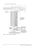
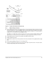
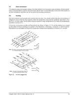
8.0 Installation Note. These drives are designed to be used only on single-ended (SE) or low voltage differential (LVD) busses. Do not install these drives on a high voltage differential (HVD) bus. The first thing to do when installing a drive is to set the drive SCSI ID and set up certain operating options. This is usually done by installing small shorting jumpers on the J5 connector (see Figure 10), or via the drive to host I/O signals on the LC model. Some users connect cables to J5 and perform the set-up using remote switches. Configure drive options For option jumper locations and definitions refer to Figures 10 and 11. Drive default mode parameters are not normally needed for installation. Refer to Section 9.3.2 for default mode parameters if they are needed. • Ensure that the SCSI ID of the drive is not the same as the host adapter. Most host adapters use SCSI ID 7 because ID 7 is the highest priority on both 8 and 16 bit data buses. • If multiple devices are on the bus set the drive SCSI ID to one that is not presently used by other devices on the bus. • If the drive is the only device on the bus, attach it to the end of the SCSI bus cable. The user, system integra- tor, or host equipment manufacturer must provide external terminators. Note. For additional information about terminator requirements, refer to Sections 9.8 and 9.9. • Set all appropriate option jumpers for desired operation prior to power on. If jumpers are changed after power has been applied, recycle the drive power to make the new settings effective. • Installation instructions are provided by host system documentation or with any additionally purchased drive installation software. If necessary see Section 10 for Seagate support services telephone numbers. • Do not remove the manufacturer's installed labels from the drive and do not cover with additional labels, as the manufacturer labels contain information required when servicing the product. Formatting • Drives are shipped from the factory low level formatted with 512 byte sectors. 8.1 Drive ID/option select header Figure 10 shows the drive ID select jumper connector. Figure 11 shows the option select jumper connector for all models. Figure 11 shows the drive's J6 jumper connector. The notes following the figures describe the functions of the various jumper positions on the connectors. Suggested part number for the jumpers used on J6 is Molex 52747-0211 (Seagate part number 77679052). A bag with the two jumper plug types is shipped with the standard OEM drives. Cheetah 15K.5 SCSI Product Manual, Rev. H 41
-
 1
1 -
2
-
3
-
4
-
5
-
6
-
7
-
8
-
9
-
10
-
11
-
12
-
13
-
14
-
15
-
16
-
17
-
18
-
19
-
20
-
21
-
22
-
23
-
24
-
25
-
26
-
27
-
28
-
29
-
30
-
31
-
32
-
33
-
34
-
35
-
36
-
37
-
38
-
39
-
40
-
41
-
 42
42 -
 43
43 -
 44
44 -
 45
45 -
 46
46 -
 47
47 -
 48
48 -
 49
49 -
 50
50 -
 51
51 -
 52
52 -
53
-
54
-
55
-
56
-
57
-
58
-
59
-
60
-
61
-
62
-
63
-
64
-
65
-
66
-
67
-
68
-
69
-
70
-
71
-
72
-
73
-
74
-
75
-
76
-
77
-
78
-
79
-
80
-
81
-
82
-
83
-
84
-
85
-
86
-
87
-
88
-
89
-
90
-
91
-
92
 |
 |