Seagate ST3146855LC Cheetah 15K.5 SCSI Product Manual - Page 76
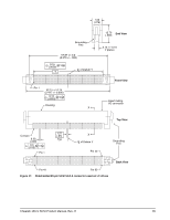
Electrical description - pin settings
 |
UPC - 836367003398
View all Seagate ST3146855LC manuals
Add to My Manuals
Save this manual to your list of manuals |
Page 76 highlights
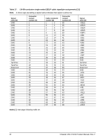
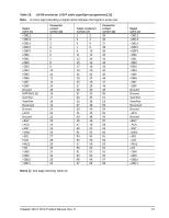
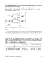
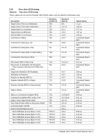
Notes [ ] for Tables 17 through 20. [1] See Section 9.6.4.1 for detailed electrical characteristics of these signals. [2] The conductor number refers to the conductor position when using 0.025-inch (0.635 mm) centerline flat ribbon cable. Other cables types may be used to implement equivalent contact assignments. [3] Connector contacts are on 0.050 inch (1.27 mm) centers. [4] Front panel LED signal; indicates drive activity for host front panel hard drive activity indicator. [5] Asserted by host to enable Motor Start option (enables starting motor via SCSI bus command). [6] Asserted by host to enable Delayed Motor Start option (motor starts at power on or after a delay of 12 sec- onds times drive ID). This and [3] above are mutually exclusive options. [7] Binary code on A3, A2, A1 and A0 asserted by host to set up SCSI bus ID in drive. [8] GND provides a means for differential devices to detect the presence of a single ended device on the bus. Drive will not operate I/O bus at Ultra2 or faster SCSI data rates if this is grounded. [9] Signals [4] through [7] are used in place of installing jumpers and cables on option select connector J6. See Section 8.1.1 notes. [10] "NC" means no connection. [11] 8 bit devices which are connected to the 16 data bit LVD I/O shall leave the following signals open: -DB8, -DB9, -DB10, -DB11, -DB12, -DB13, -DB14, -DB15, and -DBP1. 8 bit devices which are connected to the 16 data bit single-ended (SE) I/O shall have the following signals open: DB8, -DB9, -DB10, -DB11, -DB12, -DB13, -DB14, -DB15, and -DBP1. All other signals should be connected as shown. [12] Pins 38, 39, 40, 44, 78, 79, and 80 are option select pins and are tied high by the drive circuitry. The preferred electrical connection at the backplane is either open or grounded (open for the '1' setting, grounded for the '0' setting). Alternatively, these pins may be driven by a 3.3V logic device, pulled up to 3.3V through a pull-up resistor (recommended size of 10K ohm), or grounded through some other means. 9.7 Electrical description Cheetah 15K.5 SCSI drives are multimode devices. That is, their I/O circuits can operate as either singleended or low voltage differential drivers/receivers (selectable using the I/O "DIFFSENS" line). See ANSI Standard T10/1320D for detailed electrical specifications. 9.7.1 Multimode-SE and LVD alternatives When the interface "DIFFSNS" line is between -0.35 V and +0.5 V, the drive interface circuits operate singleended and up to and including 20 M transfers/s (Fast-20 or Ultra SCSI). When "DIFFSNS" is between +0.7 V and +1.9 V, the drive interface circuits operate low voltage differential and up to and including 160 M transfers/s or less (Fast-160 or Ultra320 SCSI). This multimode design does not allow dynamically changing transmission modes. Drives must operate only in the mode for which the installation and interface cabling is designed. Multimode I/O circuits used by these drives do not operate at high voltage differential levels and should never be exposed to high voltage differential environments unless the common mode voltages in the environment are controlled to safe levels for singleended and low voltage differential devices (see ANSI SPI-4 specification T10/1365D). LC and LW model drives do not have onboard terminators. Termination of the I/O lines must be provided for by the Host equipment designers or end users. LVD output characteristics Each differential signal driven by LVD interface drivers shall have the following output characteristics when measured at the disc drive connector: Steady state Low level output differential voltage = 0.32 V = < |Vs| = < 0.8 V (signal negation/logic 0) Steady state High level output differential voltage = 0.32 V = < |Vs| = < 0.8 V (signal assertion/logic 1) 70 Cheetah 15K.5 SCSI Product Manual, Rev. H
-
 1
1 -
2
-
3
-
4
-
5
-
6
-
7
-
8
-
9
-
10
-
11
-
12
-
13
-
14
-
15
-
16
-
17
-
18
-
19
-
20
-
21
-
22
-
23
-
24
-
25
-
26
-
27
-
28
-
29
-
30
-
31
-
32
-
33
-
34
-
35
-
36
-
37
-
38
-
39
-
40
-
41
-
42
-
43
-
44
-
45
-
46
-
47
-
48
-
49
-
50
-
51
-
52
-
53
-
54
-
55
-
56
-
57
-
58
-
59
-
60
-
61
-
62
-
63
-
64
-
65
-
66
-
67
-
68
-
69
-
70
-
 71
71 -
 72
72 -
 73
73 -
 74
74 -
 75
75 -
 76
76 -
 77
77 -
 78
78 -
 79
79 -
 80
80 -
 81
81 -
82
-
83
-
84
-
85
-
86
-
87
-
88
-
89
-
90
-
91
-
92
 |
 |