Seagate ST3146855LC Cheetah 15K.5 SCSI Product Manual - Page 66
SCSI interface physical description
 |
UPC - 836367003398
View all Seagate ST3146855LC manuals
Add to My Manuals
Save this manual to your list of manuals |
Page 66 highlights
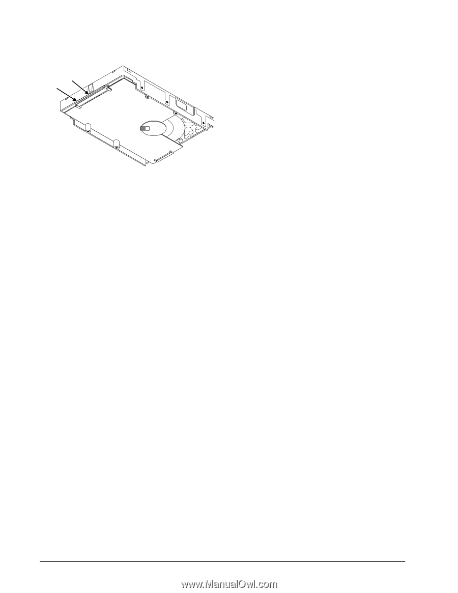
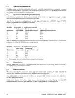
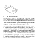
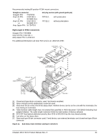
80-pin SCSI I/O Connector Pin 1 J6 Figure 14. LC model drive physical interface (80-pin J1 SCSI I/O connector) 9.6.2 SCSI interface physical description Cheetah 15K.5 SCSI drives support the physical interface requirements of the Ultra320 SCSI Parallel Interface-4 (SPI-4), and operate compatibly at the interface with devices that support earlier SCSI-2 and SCSI-3 standards. It should be noted that this is only true if the systems engineering has been correctly done, and if earlier SCSI-2 and SCSI-3 devices respond in an acceptable manner (per applicable SCSI Standards) to reject newer Ultra320 protocol extensions that they don't support. The drives documented in this manual support single-ended and low voltage differential physical interconnects (hereafter referred to as SE and LVD, respectively) as described in the corresponding ANSI SPI document referenced in the preceding paragraph. These drives implement driver and receiver circuits that can operate either SE or LVD. However, they cannot switch dynamically between SE and LVD operation. The drives typically operate on a bus with other SCSI devices. All devices on the bus must operate in the same mode, either SE or LVD, but not a mixture of these. All signals on the bus are common between all devices on the bus. This bus must be terminated at both ends with the proper impedance in order to operate correctly. Do not terminate intermediate SCSI devices. In some cases, the SCSI devices at each end have onboard termination circuits that can be enabled by installation of a jumper plug (TE) on the device. These termination circuits receive power from either a source internal to the device, or from a line in the interface cable specifically powered for that purpose. LC and LW model drives do not have onboard termination circuits. Some type of external termination circuits must be provided for these drives by the end user or designers of the equipment into which the drives will be integrated. See the ANSI T10 Standard referenced above for the maximum number of devices that can successfully operate at various interface transfer rates on SE and LVD buses. LC model drives plug into PCBA or bulkhead connectors in the host. They may be connected in a daisy chain by the host backplane wiring or PCBA circuit runs that have adequate DC current carrying capacity to support the number of drives plugged into the PCBA or bulkhead connectors. A single 80-pin I/O connector cable cannot support the DC current needs of several drives, so no cables beyond the bulkhead connectors should be used. A single drive connected via a cable to a host 80-pin I/O connector is not recommended. 60 Cheetah 15K.5 SCSI Product Manual, Rev. H
-
 1
1 -
2
-
3
-
4
-
5
-
6
-
7
-
8
-
9
-
10
-
11
-
12
-
13
-
14
-
15
-
16
-
17
-
18
-
19
-
20
-
21
-
22
-
23
-
24
-
25
-
26
-
27
-
28
-
29
-
30
-
31
-
32
-
33
-
34
-
35
-
36
-
37
-
38
-
39
-
40
-
41
-
42
-
43
-
44
-
45
-
46
-
47
-
48
-
49
-
50
-
51
-
52
-
53
-
54
-
55
-
56
-
57
-
58
-
59
-
60
-
 61
61 -
 62
62 -
 63
63 -
 64
64 -
 65
65 -
 66
66 -
 67
67 -
 68
68 -
 69
69 -
 70
70 -
 71
71 -
72
-
73
-
74
-
75
-
76
-
77
-
78
-
79
-
80
-
81
-
82
-
83
-
84
-
85
-
86
-
87
-
88
-
89
-
90
-
91
-
92
 |
 |