Seagate ST400FX0002 Pulsar XT.2 SAS Product Manual - Page 49
Installation
 |
View all Seagate ST400FX0002 manuals
Add to My Manuals
Save this manual to your list of manuals |
Page 49 highlights
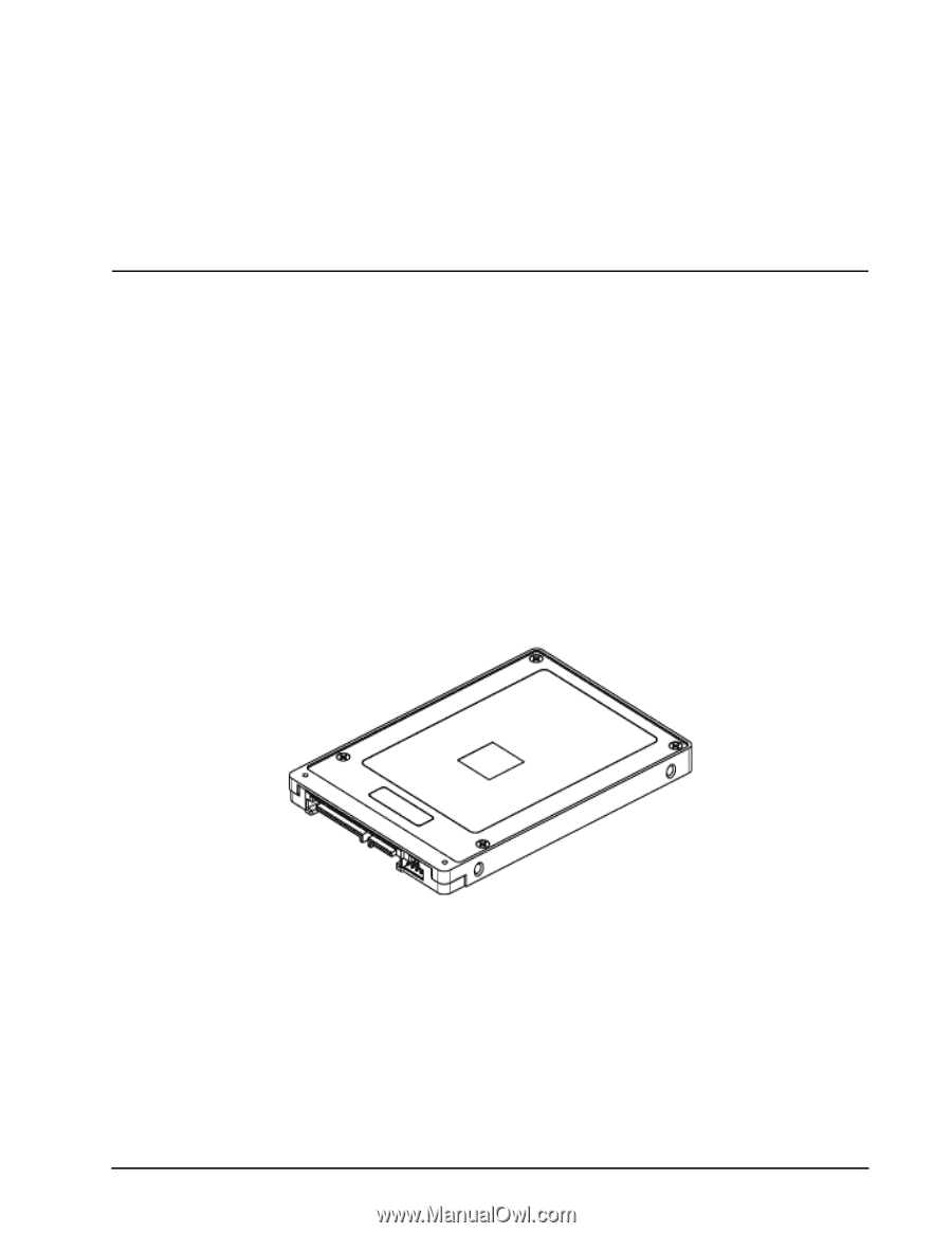
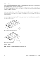
10.0 Installation Pulsar XT.2 drive installation is a plug-and-play process. There are no jumpers on the drive. SAS drives are designed to be used in a host system that provides a SAS-compatible backplane with bays designed to accommodate the drive. In such systems, the host system typically provides a carrier or tray into which the drive must be mounted. Mount the drive to the carrier or tray provided by the host system using four M3 x 0.5 metric screws. When tightening the screws, use a maximum torque of 4.5 in-lb +/- 0.45 in-lb. Do not over-tighten or force the screws. The drive can be mounted in any orientation. Note. SAS drives are designed to be attached to the host system without I/O or power cables. If the intent is to use the drive in a non-backplane host system, connecting the drive using high-quality cables is acceptable as long as the I/O cable length does not exceed 10 meters (32.8 feet). Slide the carrier or tray into the appropriate bay in the host system using the instructions provided by the host system. This connects the drive directly to the system's SAS connector. The SAS connector is normally located on a SAS backpanel. See Section 11.4.1 for additional information about these connectors. Power is supplied through the SAS connector. The drive is shipped from the factory low-level formatted in 512-byte logical blocks. Reformatting the drive is only required if the application requires a different logical block size. Figure 12. Physical interface 10.1 Drive orientation The drive may be mounted in any orientation. All drive performance characterizations, however, have been done with the drive in horizontal (level) and vertical (drive on its side) orientations, which are the two preferred mounting orientations. Pulsar XT.2 SAS Product Manual, Rev. B 41
-
 1
1 -
2
-
3
-
4
-
5
-
6
-
7
-
8
-
9
-
10
-
11
-
12
-
13
-
14
-
15
-
16
-
17
-
18
-
19
-
20
-
21
-
22
-
23
-
24
-
25
-
26
-
27
-
28
-
29
-
30
-
31
-
32
-
33
-
34
-
35
-
36
-
37
-
38
-
39
-
40
-
41
-
42
-
43
-
 44
44 -
 45
45 -
 46
46 -
 47
47 -
 48
48 -
 49
49 -
 50
50 -
 51
51 -
 52
52 -
 53
53 -
 54
54 -
55
-
56
-
57
-
58
-
59
-
60
-
61
-
62
-
63
-
64
-
65
-
66
-
67
-
68
-
69
-
70
-
71
-
72
-
73
-
74
 |
 |