Seagate ST9900805SS Savvio 10K.4 FC Product Manual - Page 46
Drive mounting
 |
View all Seagate ST9900805SS manuals
Add to My Manuals
Save this manual to your list of manuals |
Page 46 highlights
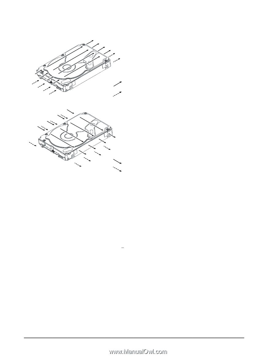
If forced air is necessary, possible air-flow patterns are shown in Figure 8. The air-flow patterns are created by fans either forcing or drawing air as shown in the illustrations. Conduction, convection, or other forced air-flow patterns are acceptable as long as the temperature measurement guidelines of Section 6.5.1 are met. Above unit Under unit Note. Air flows in the direction shown (back to front) or in reverse direction (front to back) Note. Air flows in the direction shown or in reverse direction (side to side) Figure 8. Air flow Above unit Under unit Note. Image of the HDA may not represent actual product, for reference only 8.4 Drive mounting Mount the drive using the bottom or side mounting holes. If you mount the drive using the bottom holes, ensure that you do not physically distort the drive by attempting to mount it on a stiff, non-flat surface. The allowable mounting surface stiffness is 80 lb/in (14.0 N/mm). The following equation and paragraph define the allowable mounting surface stiffness: K x X = F < 15lb = 67N where K is the mounting surface stiffness (units in lb/in or N/mm) and X is the out-of-plane surface distortion (units in inches or millimeters). The out-of-plane distortion (X) is determined by defining a plane with three of the four mounting points fixed and evaluating the out-of-plane deflection of the fourth mounting point when a known force (F) is applied to the fourth point. Note. Before mounting the drive in any kind of 3.5-inch to 5.25-inch adapter frame, verify with Seagate Technology that the drive can meet the shock and vibration specifications given herein while mounted in such an adapter frame. Adapter frames that are available may not have a mechanical structure capable of mounting the drive so that it can meet the shock and vibration specifications listed in this manual. 40 Savvio 10K.4 FC Product Manual, Rev. A
-
 1
1 -
2
-
3
-
4
-
5
-
6
-
7
-
8
-
9
-
10
-
11
-
12
-
13
-
14
-
15
-
16
-
17
-
18
-
19
-
20
-
21
-
22
-
23
-
24
-
25
-
26
-
27
-
28
-
29
-
30
-
31
-
32
-
33
-
34
-
35
-
36
-
37
-
38
-
39
-
40
-
 41
41 -
 42
42 -
 43
43 -
 44
44 -
 45
45 -
 46
46 -
 47
47 -
 48
48 -
 49
49 -
 50
50 -
 51
51 -
52
-
53
-
54
-
55
-
56
-
57
-
58
-
59
-
60
-
61
-
62
-
63
-
64
-
65
-
66
-
67
-
68
-
69
-
70
-
71
-
72
-
73
-
74
-
75
-
76
-
77
-
78
-
79
-
80
-
81
-
82
-
83
-
84
 |
 |