Seagate ST9900805SS Savvio 10K.4 FC Product Manual - Page 66
FC-AL transmitters and receivers
 |
View all Seagate ST9900805SS manuals
Add to My Manuals
Save this manual to your list of manuals |
Page 66 highlights
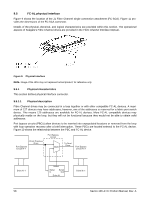
Table 21: FC-SCA pin descriptions Pin Signal name Signal type 1* -EN bypass port A Low Voltage TTL output 2* 12 Volts 3* 12 Volts 4* 12 Volts 5* -Parallel ESI 6* Ground[1] 7* Active LED out Open collector out 8* Reserved 9* Start_1[2] 10* Start_2[2] TTL input TTL input 11* -EN bypass port B Low Voltage TTL output 12* SEL_6 TTL input/output 13* SEL_5 TTL input/output 14* SEL_4 TTL input 15* SEL_3 TTL input/output 16* Fault LED out Open collector out 17* DEV_CTRL_CODE_2[2] TTL input 18* DEV_CTRL_CODE_1[2] TTL input 19* 5 Volts 20* 5 Volts Pin Signal name Signal type 21 12 Volts charge 22 Ground 23 Ground 24* +Port A_in FC Diff. input pair 25* -Port A_in 26 Ground 27* +Port B_in FC Diff. input pair 28* -Port B_in 29 Ground 30* +Port A_out FC Diff. output pair 31* -Port A_out 32 Ground 33* +Port B_out FC Diff. output pair 34* -Port B_out 35 Ground 36 SEL_2 TTL input/output 37 SEL_1 TTL input/output 38 SEL_0 TTL input/output 39 DEV_CTRL_CODE_0[2 TTL input 40 5 Volts charge *Short pins in mating backpanel connector. [1] This pin may be connected to external logic to detect the presence of the drive. The drive connects this pin to the common ground. [2] Pins 9, 10, 17, 18, and 39 are option select pins and are tied high by the drive circuitry. The preferred electrical connection at the backplane is either open or grounded (open for the '1' setting, grounded for the '0' setting). Alternatively, these pins may be driven by a 3.3V logic device, pulled up to 3.3V through a pull-up resistor (recommended size of 10K ohm), or grounded through some other means. 9.5.5 FC-AL transmitters and receivers A typical FC-AL differential copper transmitter and receiver pair is shown in Figure 12. The receiver is required to provide the AC coupling to eliminate ground shift noise. TX Transmitter 100 TY .01 RX Differential Transfer Medium Receiver 100 .01 RY Figure 12. FC-AL transmitters and receivers 60 Savvio 10K.4 FC Product Manual, Rev. A
-
 1
1 -
2
-
3
-
4
-
5
-
6
-
7
-
8
-
9
-
10
-
11
-
12
-
13
-
14
-
15
-
16
-
17
-
18
-
19
-
20
-
21
-
22
-
23
-
24
-
25
-
26
-
27
-
28
-
29
-
30
-
31
-
32
-
33
-
34
-
35
-
36
-
37
-
38
-
39
-
40
-
41
-
42
-
43
-
44
-
45
-
46
-
47
-
48
-
49
-
50
-
51
-
52
-
53
-
54
-
55
-
56
-
57
-
58
-
59
-
60
-
 61
61 -
 62
62 -
 63
63 -
 64
64 -
 65
65 -
 66
66 -
 67
67 -
 68
68 -
 69
69 -
 70
70 -
 71
71 -
72
-
73
-
74
-
75
-
76
-
77
-
78
-
79
-
80
-
81
-
82
-
83
-
84
 |
 |
