Seagate ST9900805SS Savvio 10K.1 SCSI Product Manual - Page 65
Terminator requirements
 |
View all Seagate ST9900805SS manuals
Add to My Manuals
Save this manual to your list of manuals |
Page 65 highlights
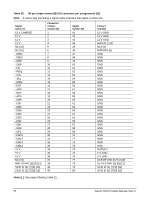
LVD input characteristics Each differential signal received by LVD interface receiver circuits shall have the following input characteristics when measured at the disc drive connector: Steady state Low level input differential voltage = 0.030 V = < Vin = < 3.6 V (signal negation/logic 0) Steady state High level input differential voltage = -3.6 V = < Vin = < -0.030 V (signal assertion/logic 1) Differential voltage = +0.030 V minimum with common-mode voltage range 0.845 V = < Vcm = < 1.655 V. (T10/1302D revision 14, section A.3.2). Single Ended Circuitry VCCA LVD Signal Drivers LVD Receiver VCCB Single Ended Receiver Single Ended Negation Driver Single Ended Ground Driver LVD Signal Drivers Single Ended Assertion Driver Ground Single Ended: GND LVD: +Signal -Signal -Signal Figure 16. Typical SE-LVD alternative transmitter receiver circuits 9.7.1.1 General cable characteristics The 80-pin connector option provided on LC models is intended for use on drives that plug directly into backplane connector in the host equipment. In such installations, all backplane wiring segments are subject to the electromagnetic concepts presented in Standard T10/1365D, Rev. 3, Section 6. For LC model drives, installations with cables are not recommended. 9.7.1.2 Single-ended drivers/receivers Single-ended I/O pin assignments are shown in Table 20. The LC model drives do not require an I/O cable. These models are designed to connect directly to a back panel connector. 9.8 Terminator requirements These drives do not have onboard internal terminators. The user, systems integrator or host equipment manufacturer must provide a terminator arrangement external to the drive when termination is required. LC model drives are designed to be plugged into a backpanel connector without cabling. 9.8.1 Terminator power These drives cannot furnish terminator power because no conductors in the 80-pin I/O connector are devoted to terminator power. Savvio SCSI Product Manual, Rev. D 59
-
 1
1 -
2
-
3
-
4
-
5
-
6
-
7
-
8
-
9
-
10
-
11
-
12
-
13
-
14
-
15
-
16
-
17
-
18
-
19
-
20
-
21
-
22
-
23
-
24
-
25
-
26
-
27
-
28
-
29
-
30
-
31
-
32
-
33
-
34
-
35
-
36
-
37
-
38
-
39
-
40
-
41
-
42
-
43
-
44
-
45
-
46
-
47
-
48
-
49
-
50
-
51
-
52
-
53
-
54
-
55
-
56
-
57
-
58
-
59
-
 60
60 -
 61
61 -
 62
62 -
 63
63 -
 64
64 -
 65
65 -
 66
66 -
 67
67 -
 68
68 -
 69
69 -
 70
70 -
71
-
72
-
73
-
74
-
75
-
76
-
77
-
78
 |
 |
