Seagate ST9900805SS Savvio 10K.1 SCSI Product Manual - Page 67
Notes., Table 22, Disc drive SCSI timing Continued
 |
View all Seagate ST9900805SS manuals
Add to My Manuals
Save this manual to your list of manuals |
Page 67 highlights
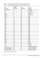
Table 22: Disc drive SCSI timing (Continued) These values are not current Savvio SCSI values, but are listed for information only. Description Next CDB Byte Access (Byte 8 of 10) Next CDB Byte Access (Byte 9 of 10) Next CDB Byte Access (Byte 10 of 10) Data In Byte Transfer (parameter) Data Out Byte Transfer (parameter) Next Data In Byte Access (parameter) Next Data Out Byte Access (parameter) Data In Byte Transfer (media) [2] Data Out Byte Transfer (media) [2] Next Data In Byte access (media [2] Next Data Out Byte access (media [2] MSG IN Byte Transfer MSG OUT Byte Transfer STATUS Byte Transfer Synchronous Data Transfer Characteristics: Request Signal Transfer Period [3] Waveform symbol [1] T23.10.8 T23.10.9 T23.10.10 T24 T25 T26 T27 T28 T29 T30 T31 T32 T33 T34 - Waveform table [1] 4.5-4 4.5-4 4.5-4 4.5-12 4.5-13 4.5-12 4.5-13 4.5-12 4.5-13 4.5-12 4.5-13 4.5-5,7,8,14,15 4.5-2 4.5-5,8,15 Typical timing 0.12 μs ±1 μs 0.12 μs ±1 μs 0.12 μs ±1 μs 0.04 μs 0.04 μs 0.12 μs 0.12 μs 0.04 μs 0.04 μs 0.12 μs 0.12 μs 0.04 μs 0.04 μs 0.04 μs - various (800 ns max) Notes. [1] See the Timing examples section of the SCSI Interface Product Manual. [2] Maximum SCSI asynchronous interface transfer rate is given in Section 4.2.3 of this manual. [3] Synchronous Transfer Period is determined by negotiations between an Initiator and a Drive. The Drive is capable of setting periods as given in Section 9.5. See also the Synchronous data transfer section and the Extended messages section of the SCSI Command Reference Manual for a description of synchronous data transfer operation. Savvio SCSI Product Manual, Rev. D 61
-
 1
1 -
2
-
3
-
4
-
5
-
6
-
7
-
8
-
9
-
10
-
11
-
12
-
13
-
14
-
15
-
16
-
17
-
18
-
19
-
20
-
21
-
22
-
23
-
24
-
25
-
26
-
27
-
28
-
29
-
30
-
31
-
32
-
33
-
34
-
35
-
36
-
37
-
38
-
39
-
40
-
41
-
42
-
43
-
44
-
45
-
46
-
47
-
48
-
49
-
50
-
51
-
52
-
53
-
54
-
55
-
56
-
57
-
58
-
59
-
60
-
61
-
 62
62 -
 63
63 -
 64
64 -
 65
65 -
 66
66 -
 67
67 -
 68
68 -
 69
69 -
 70
70 -
 71
71 -
 72
72 -
73
-
74
-
75
-
76
-
77
-
78
 |
 |
