Sennheiser EM 1036 Instructions for Use - Page 8
Introduction, Variations, Mechanics, Mains, connection, connection, Connections, headphones
 |
View all Sennheiser EM 1036 manuals
Add to My Manuals
Save this manual to your list of manuals |
Page 8 highlights
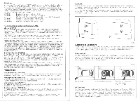
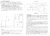
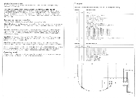
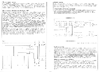
Introduction The new Sennheiser multi-channel receiver EM 1036 is capable of meeting all professional requirements. The most outstanding characteristics of this receiver are: multi-channel capacity, diversity operation without additional equipment high transmission quality due to the "HiDyn" noise reduction system, users orientated design and capability of expansion due to the 19" module technique. The receiver is available in the following versions: EM 1036: EM 1036 R: wideband, frequency range 30-45 MHz wideband, freauencv ramie 30 -45 MHz Licensed for broadcasting stations in the Federal Republic of Germany. EM 1036-7: EM 1036-9: EM 1036-90: narrowband, frequency range 30-45 MHz.. narrowband, frequency range 138-250 MHz. wideband, frequency range 138 -250 MHz. Brief description of the indivudual components Chassis EMC 1036 The 19"-Chassis EMC 1036 provides space lor the monitor unit EMM 1036 and 6 receiver modules type EME 1036. It contains the power supply, the wiring for the rack connectors to the seperate modules as well as the in- and output sockets for the RF and AF-connections. The chassis can be fitted into 19" racks. but it can also be used as a table top unit in connection with the housing EMG 1036 or the EMK 1036 carrying case. Vacant spaces can be closed off with cover plates EMB 1026. Monitor module EMM 1036 The monitor module EMM 1036 contains a set of push buttons with which the AF-output signals of the receiver modules are selected to be monitored individually or as a sum through a headphone. Besides the set of push-buttons and the monitor output, there are on the front panel the mains switch and 3 LEDs - two indicating the switchable supply voltage with which e. g. antenna amplifiers can be led (see also section "Antennas and RE-connections"). The third shows the state of operation. Receiver module EME 1036 The module EME 1036 is single-channel to achieve optimum selectivity. The controls are dearly arranged on the front plate. A LED display shows in logarythmic scale the RF input voltage and, optionally by means of a push-button switch, the modulation in percentage. A squelch control, accessible through an opening in the front plate, permits varying the threshold for the built-in electronic squelch. Diversity operation of two adjacent receiver modules (1 and 2, 3 and 4 etc.) is possible without further diversity equipment by simply operating a switch. The transmission reliability available with diversity operation is further increased by the built-in noise suppression system "HiDyn". Variations Receiver module EME 1036 Wdeband receiver module for one frequency in the range 30 - 45 MHz. Receiver module EME 1036R Wideband receiver module for one frequency in the range 32.55 - 38.05 MHz. Receiver module EME 1036-7 Narrowband receiver module for one frequency in the range 30 - 45 MHz. Receiver module EME 1036-9 Narrowbend receiver module for one frequency in the range of 138 - 250 MHz Receiver module EME 1036-90 Wideband receiver module for one frequency in the range of 138 - 250 MHz. 11 Mechanics The individual modules are fastened on the chassis with quick-release locks. Turning clockwise or anticlockwise by 90° opens the locking and the module can be removed by pulling it out of the chassis, towards the front. Turning the feet of the set by 180° makes the EM 1036 stackable with other sets. To do so, screws A and B must be losened, the feet turned, and the screws fastened again (Fig. 5). eB 1 2. Fig. 5 Installing the receiver The receiver chassis can be fitted into 19" racks, but it can also be used as a table top unit in connection with the housing EMG 1036 or the EMK 1036 carrying case. In any case one should make sure that the ventilation in the receiver is not obstructed in any way. Mains connection The chassis EMC 1036 leaves the factory pre-set for 220V/50 - 60 Hz operation. If it is to be operated on mains voltages of 110V or 240V, this change-over can be done by using the voltage selector (15), which is made accessible by opening the flap (14). Behind this flap, you will also find the fuse holder (t6). Fig. 6 t I] Igutj Opening the lisp AF-connection Orange-over of mains wage ChangingRIG lure 220/240 V: 0,63 AT 110V: 1.25AT The AF-output signals of the different receiver modules are available at the outputs (20) floating and balanced, with a level of + 6dBm = 1.55V (al nominal swing). This level may, if necessary, be adjusted to a value between OdBm and + 10dBm resp. attenuated by 20dB with a switch (see "Adjusting AF-voltages'). Since, in diversity operation, both AE-outputs of one diversity pair deliver the same signal, only one AF-connedion lead per channel is needed. Connections for headphones The AF-output signals of the individual receiver modules can be monitored through headphones. With the set of push-puttons (8) the signal of each receiver module or the sum of the signals of all receiver modules can be switched onto the headphone output (9). The monitoring volume can be adjusted with the volume control (10). With diversity operation always the receiver module of a diversity pair is switched onto the headphone output, which delivers the best signal (see Fig. 8). 12
-
 1
1 -
2
-
 3
3 -
 4
4 -
 5
5 -
 6
6 -
 7
7 -
 8
8 -
 9
9 -
 10
10 -
 11
11 -
 12
12 -
 13
13 -
14
-
15
-
16
 |
 |
