Sharp AX1200S RK-12S30 Installation Instructions
Sharp AX1200S - 22" SuperSteam Oven Manual
 |
UPC - 074000617667
View all Sharp AX1200S manuals
Add to My Manuals
Save this manual to your list of manuals |
Sharp AX1200S manual content summary:
- Sharp AX1200S | RK-12S30 Installation Instructions - Page 1
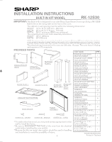
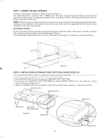
INSTALLATION INSTRUCTIONS BUILT-IN KIT MODEL RK-12S30 IMPORTANT: This Built-In Kit is designed for use with Sharp SuperSteam Ovens specifying a RK-12S30 Built-In Kit on the rating label on the front of the oven. The cabinet or wall opening must be within the following dimensions: HEIGHT 19" to 19 - Sharp AX1200S | RK-12S30 Installation Instructions - Page 2
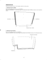
PREPARATION Follow the directions from 1 to 5 to attach cushions to some parts. 1. EXHAUST DUCT UPPER Remove the backing paper from each CUSHION 1. Attach the CUSHIONS 1 to each side flange of the EXHAUST DUCT UPPER as shown in - Sharp AX1200S | RK-12S30 Installation Instructions - Page 3
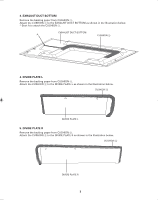
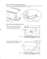
3. EXHAUST DUCT BOTTOM Remove the backing paper from CUSHION 3. Attach the CUSHION 3 to the EXHAUST DUCT BOTTOM as shown in the Illustration below. * Start A to attach the CUSHION 3. EXHAUST DUCT BOTTOM A CUSHION 3 4. DIVIDE PLATE L Remove the backing paper from CUSHION 4. Attach the CUSHION 4 - Sharp AX1200S | RK-12S30 Installation Instructions - Page 4
support the weight of the oven (about 150 lbs., 68.1 kg) and should be level for proper operation of the oven. NOTE: While the proper functioning of the oven for any such requirement. ELECTRICAL SUPPLY At the rear of the opening, provide a 3 pronged, polarized, electrical outlet, 120 volt A.C., 15 - Sharp AX1200S | RK-12S30 Installation Instructions - Page 5
DUCT BOTTOM as shown in Figure 3-A. EXHAUST DUCT BOTTOM Figure 3 STEP 4: EXHAUST DUCT BACK INSTALLATION 1 Remove 2 screws (#1) from upper both sides of the oven as shown in Figure 4-A to install the EXHAUST DUCT BACK. (Save 2 screws to be used at step 4-2.) #1 Projection Figure 3-A Figure - Sharp AX1200S | RK-12S30 Installation Instructions - Page 6
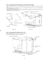
L SCREW (A) SCREW (A) SCREW (A) EXHAUST DUCT UPPER SCREW (A) Figure 5-A EXHAUST DUCT BACK Figure 5-B STEP 6: INSTALLATION OF EXHAUST DUCT LEFT 1 Attach EXHAUST DUCT LEFT to the left wall of the oven. 2 Tighen with 6 screws (A) as shown in Figure 6. EXHAUST DUCT UPPER SCREW (A) EXHAUST DUCT - Sharp AX1200S | RK-12S30 Installation Instructions - Page 7
line of opening and mark front edge. 2 Place the oven on a table or stand positioned in front of the cabinet where the oven is to be installed. One person should hold the oven while the other connects it to the electrical outlet. 3 Install the oven into the shelf with adjusting mark on EXHAUST DUCT - Sharp AX1200S | RK-12S30 Installation Instructions - Page 8
SCREWS (B) as shown in Figures 8-B. SCREW (B) Figure 8-B STEP 9: FRAME ASSEMBLY INSTALLATION 1 Attach FRAME ASSEMBLY and tighten 4 SCREWS (C) as shown in Figure 9 and please call SHARP's Customer Assistance Center 1-800-BE-SHARP. ® SHARP ELECTRONICS CORPORATION Sharp Plaza, Mahwah, NJ 07495-1163 8
-
 1
1 -
 2
2 -
 3
3 -
 4
4 -
 5
5 -
 6
6 -
 7
7 -
8
 |
 |
1
PART NAME
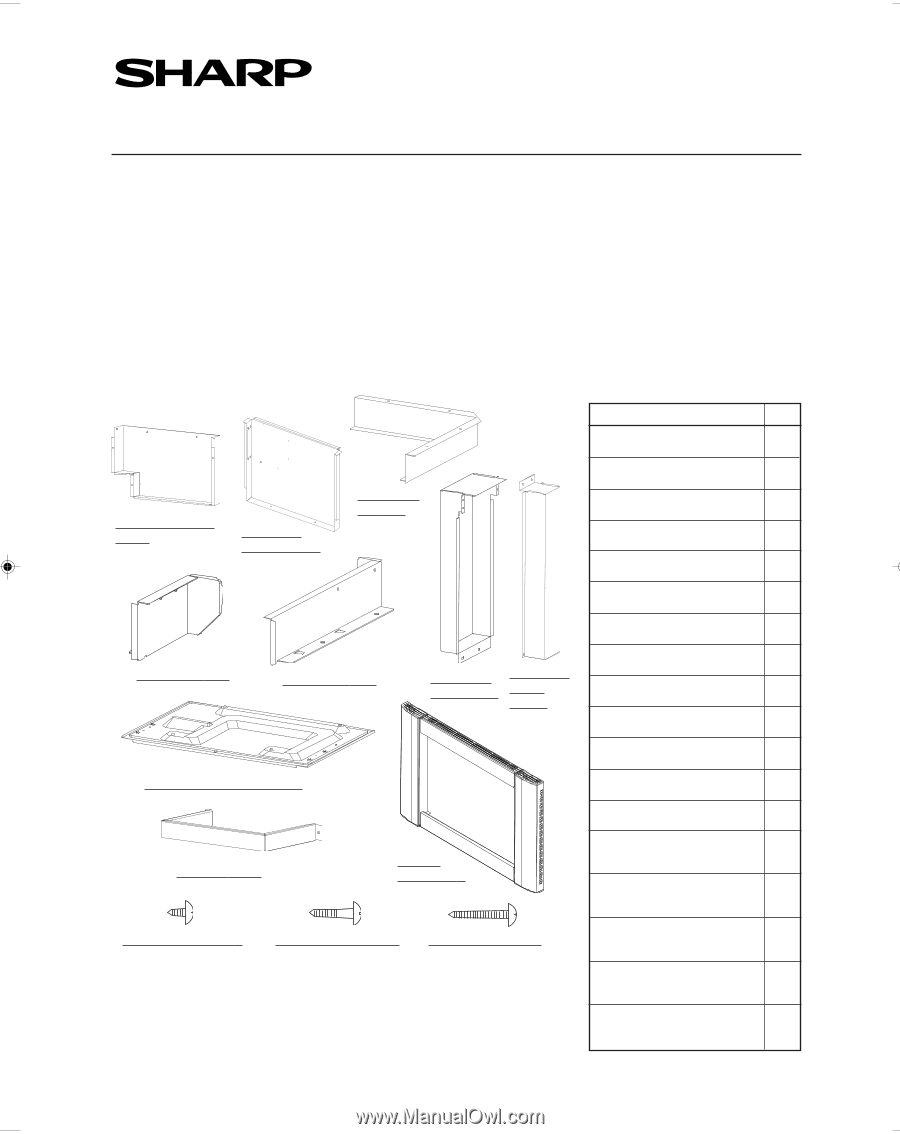
EXHAUST DUCT BACK
PDVC-B107WRWZ
EXHAUST DUCT UPPER
PDVC-B105WRWZ
DIVIDE PLATE L
PSKR-A486WRWZ
DIVIDE PLATE R
PSKR-A487WRWZ
RECTIFIER PLATE L
PSKR-A484WRWZ
EXHAUST DUCT LEFT
PDVC-B108WRWZ
EXHAUST DUCT RIGHT
PDUC-B117WRWZ
EXHAUST DUCT BOTTOM
PDVC-B106WRWZ
FRAME ASSEMBLY
FDEC-A004WRKZ
SCREW(A)
XHTS740P08000
SCREW(B)
XMMS841P13000
SCREW(C)
XMSS827P25000
REAR SPACER
PSPAFA003WRWZ
CUSHION
1
5
/
8
" x 16",
15 mm x 405 mm
PCUS-A245WRPZ
CUSHION
2
1
/
4
" x 24
3
/
8
",
5 mm x 618 mm
PCUS-A247WRPZ
CUSHION
3
1
1
/
8
" x 27
1
/
8
",
30 mm x 689 mm
PCUS-A249WRPZ
CUSHION
4
1
/
4
" x 12",
5 mm x 305 mm
PCUS-A251WRPZ
CUSHION
5
1
/
4
" x 15",
5 mm x 382 mm
PCUS-A253WRPZ
INSTALLATION INSTRUCTIONS
BUILT-IN KIT MODEL
IMPORTANT:
This Built-In Kit is designed for use with Sharp SuperSteam Ovens specifying a RK-12S30
Built-In Kit on the rating label on the front of the oven.
The cabinet or wall opening must be within the following dimensions:
HEIGHT
19" to 19
1
/
8
" (482 mm - 486 mm)
WIDTH
28" to 28
1
/
4
" (710 mm - 719 mm)
DEPTH
23
1
/
4
" minimum (509.5 mm minimum)
The completed built-in kit frame assembly dimensions:
HEIGHT
19
1
/
2
" (495mm)
WIDTH
30" (762mm)
NOTE: The bottom of the cut-out opening for built-in use must be 36 inches (915 mm) or higher from the floor.
PLEASE READ THESE INSTRUCTIONS THOROUGHLY BEFORE BEGINNING INSTALLATION!
The electrical requirements for this oven are 120 volts, 15 amps. The oven has a 5-15 plug
and requires a 5-15 receptacle.
RK-12S30
Q'TY
1
1
1
1
1
1
1
1
1
23
2
4
1
2
1
1
1
1
* For walls other than wood, you may need screws appropriate for that
wall to install the frame.
*
Be sure to DISCONNECT THE PLUG of the oven from the electrical
outlet before installing the oven and kit.
* Because the kits are metal, due caution should be used in handling
and installation to avoid the possibility of injury.
PROVIDED PARTS
SCREW (C) - LONG
EXHAUST DUCT BOTTOM
EXHAUST DUCT
BACK
EXHAUST
DUCT UPPER
EXHAUST
DUCT
RIGHT
DIVIDE PLA
TE L
DIVIDE PLA
TE R
FRAME
ASSEMBL
Y
RECTIFIER
PLA
TE L
EXHAUST
DUCT LEFT
REAR SP
ACER
SCREW (B) - MIDDLE
SCREW (A) - SHOR
T
TINSEB184WRRZ-D92
Printed in Thailand