Sharp AX1200S RK-12S30 Installation Instructions - Page 7
Step 8, Oven Installation, Step 7, Installation Of Exhaust Duct Right
 |
UPC - 074000617667
View all Sharp AX1200S manuals
Add to My Manuals
Save this manual to your list of manuals |
Page 7 highlights
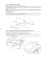
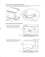
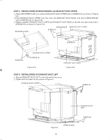
STEP 7: INSTALLATION OF EXHAUST DUCT RIGHT 1 Attach EXHAUST DUCT RIGHT to the right wall of the oven. 2 Tighten with 4 SCREWS (A) as shown in the Figure 7. EXHAUST DUCT UPPER SCREW (A) EXHAUST DUCT RIGHT SCREW (A) Figure 7 DIVIDE PLATE R STEP 8: OVEN INSTALLATION CAUTION: Never hold the handle when moving the oven. Two persons are required to install the oven. 1 Establish center line of opening and mark front edge. 2 Place the oven on a table or stand positioned in front of the cabinet where the oven is to be installed. One person should hold the oven while the other connects it to the electrical outlet. 3 Install the oven into the shelf with adjusting mark on EXHAUST DUCT BOTTOM to the center line marked on front edge as shown in Figures 8 and 8-A. Then push the oven until the flange of EXHAUST DUCT BOTTOM touches the edge of the wall or cabinet opening. Avoid pinching the cord between the oven and any wall as shown in Figure 8. Figure 8-A Flange 28" - 28 1/4" (710 mm - 719 mm) Figure 8 CL 7
-
 1
1 -
 2
2 -
 3
3 -
 4
4 -
 5
5 -
 6
6 -
 7
7 -
 8
8
 |
 |
