Sharp DV-NC70U Service Manual - Page 1
Sharp DV-NC70U Manual
 |
View all Sharp DV-NC70U manuals
Add to My Manuals
Save this manual to your list of manuals |
Page 1 highlights
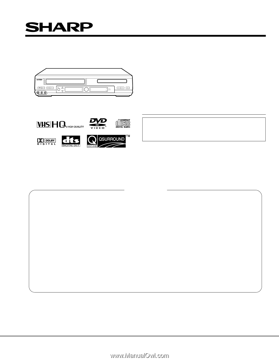
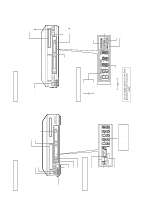
POWER EJECT/STOP / REW PLAY AV 2 IN VIDEO L(MONO)-AUDIO-R REC CH DV-NC70U/C DV-NC72U SERVICE MANUAL S62K3DV-NC70U VCR/DVD COMBINATION MODEL DV-NC70U VCR/DVD SELECTOR TIMER VCR DVD PLAY STOP OPEN/CLOSE DV-NC70C MODELS DV-NC72U In the interests of user-safety (Required by safety regulations in some countries) the set should be restored to its original condition and only parts identical to those specified be used. CONTENTS Page 1. IMPORTANT SERVICE NOTES ...2 2. FEATURES ...4 3. SPECIFICATIONS ...4 4. PART NAMES ...6 5. MAINTENANCE CHECK ITEMS AND EXECUTION TIME 9 6. DISASSEMBLY METHOD ...10 7. OPERATION OF PICKUP ...14 8. ADJUSTMENT, REPLACEMENT AND ASSEMBLY OF MECHANICAL UNITS 15 9. TEST MODE ...38 10. TROUBLESHOOTING ...41 11. BLOCK DIAGRAMS ...52 12. SCHEMATIC DIAGRAMS ...60 13. PRINTED WIRING BOARD ASSEMBLIES 74 14. REPLACEMENT PARTS LIST ...89 15. PACKING OF THE SET ...106 SHARP CORPORATION 1 This document has been published to be used for after sales service only. The contents are subject to change without notice.
-
 1
1 -
 2
2 -
 3
3 -
 4
4 -
 5
5 -
 6
6 -
 7
7 -
8
-
9
-
10
-
11
-
12
-
13
-
14
-
15
-
16
-
17
-
18
-
19
-
20
-
21
-
22
-
23
-
24
-
25
-
26
-
27
-
28
-
29
-
30
-
31
-
32
-
33
-
34
-
35
-
36
-
37
-
38
-
39
-
40
-
41
-
42
-
43
-
44
-
45
-
46
-
47
-
48
-
49
-
50
-
51
-
52
-
53
-
54
-
55
-
56
-
57
-
58
-
59
-
60
-
61
-
62
-
63
-
64
-
65
-
66
-
67
-
68
-
69
-
70
-
71
-
72
-
73
-
74
-
75
-
76
-
77
-
78
-
79
-
80
-
81
-
82
-
83
-
84
-
85
-
86
-
87
-
88
-
89
-
90
-
91
-
92
 |
 |