Sharp DV-SL90UM Service Manual
Sharp DV-SL90UM Manual
 |
View all Sharp DV-SL90UM manuals
Add to My Manuals
Save this manual to your list of manuals |
Sharp DV-SL90UM manual content summary:
- Sharp DV-SL90UM | Service Manual - Page 1
MODEL DV-SL90UM CONTENTS Page SPECIFICATIONS ...1-1-1 LASER BEAM SAFETY PRECAUTIONS 1-2-1 IMPORTANT SAFEGUARDS AND PRECAUTIONS 1-3-1 STANDARD NOTES FOR SERVICING 1-4-1 OPERATING CONTROLS AND FUNCTIONS 1-5-1 CABINET DISASSEMBLY INSTRUCTIONS 1-6-1 FIRMWARE RENEWAL MODE ...1-7-1 TROUBLESHOOTING - Sharp DV-SL90UM | Service Manual - Page 2
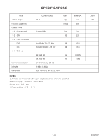
SPECIFICATIONS ITEM 1 Video Output 2 Coaxial Digital Out 3 Audio (PCM) 3-1. Output Level 3-2. S/N 3-3. Freq. Response DVD CD 3-4. THD +N 4 Power consumption 5 Weight 6 Dimension CONDITIONS 75 Ω UNIT Vpp mVpp 1 kHz 0 dB Vrm dB fs=48 kHz 20 ~ 22 kHz dB fs=44.1 kHz - Sharp DV-SL90UM | Service Manual - Page 3
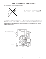
LASER BEAM SAFETY PRECAUTIONS This DVD player uses a pickup that emits a laser beam. Do not look directly at the laser beam coming from the pickup or allow it to strike against - Sharp DV-SL90UM | Service Manual - Page 4
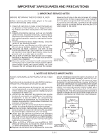
TO EXPOSED METAL PARTS 0.15 F TEST PROBE CONNECT TO KNOWN EARTH GROUNG 1. NOTES DE SERVICE IMPORTANTES AVANT DE RENDRE LE REPRODUCTOR DE VíDEO DVD Avant de rendre le reproductor de vídeo DVD à l'utilisateur, effectuer les vérifications de sécurité suivantes. 1. Vérifier toutes les gaines de fil - Sharp DV-SL90UM | Service Manual - Page 5
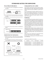
every male connector is indicated as shown. < Bottom View > Pin 1 Instructions for Connectors 1. When you connect or disconnect the FFC (Flexible Foil Connector obtain lead-free wire solder or soldening bit, contact our service station or service ranch in your area. Soldering As the melting point of - Sharp DV-SL90UM | Service Manual - Page 6
or wire to which solder will not adhere (iron wire). When heating the pins, use a fine tip soldering iron or a hot air desoldering machine. (Fig. S-1-4) Sharp Pin Fine Tip Soldering Iron Fig. S-1-4 (3) Bottom of the flat pack-IC is fixed with glue to the CBA; when removing entire flat pack-IC - Sharp DV-SL90UM | Service Manual - Page 7
(4) Bottom of the flat pack-IC is fixed with glue to the CBA; when removing entire flat pack-IC, first apply soldering iron to center of the flat pack-IC and heat up. Then remove (glue will be melted). (Fig. S-1-6) (5) Release the flat pack-IC from the CBA using tweezers. (Fig. S-1-6) Note: When - Sharp DV-SL90UM | Service Manual - Page 8
Instructions for Handling Semi-conductors Electrostatic breakdown of the semi-conductors may occur due to a potential difference caused by electrostatic charge during unpacking or repair work. 1. - Sharp DV-SL90UM | Service Manual - Page 9
to the previous operation. 18. Arrow Buttons ( / / / ) Use when making settings while watching the display on a TV screen. 19. MENU Button Displays the DVD menus and MP3 file lists. 20. STOP Button Stops operation of the disc. 21. FWD Button Fast forwards playback to a desired point. 22. SKIP Button - Sharp DV-SL90UM | Service Manual - Page 10
the progressive scan system is activated. P.SCAN DVD VCD Displays a type of the disc which is inserted on the tray. DVD: DVD CD: Audio CD, MP3, JPEG, Kodak Picture VCD: Video CD Lights up when playing back in slow mode. (DVD) Lights up when the inserted disc is being played back. Displays the - Sharp DV-SL90UM | Service Manual - Page 11
INSTRUCTIONS 1. Disassembly Flowchart This flowchart indicates the disassembly steps to gain access to item(s) to be serviced. When reassembling, follow the steps in reverse order. Bend, route, and dress the cables as they were originally. [1] Top Case [2] Front Assembly [3] Reinforce Plate [4] DVD - Sharp DV-SL90UM | Service Manual - Page 12
Top Case (S-1) (L-1) (L-3) (L-1) Fig. 1 (L-2) [2] Front Assembly Fig. 2 (S-2) [3] Reinforce Plate CN201 CN301 (S-3B) (S-3A) CN601 CN401 A [4] DVD Main CBA Unit Solder Short lands OR Short lands Short the three short lands by soldering. (Either of two places.) Solder FPC Cable View - Sharp DV-SL90UM | Service Manual - Page 13
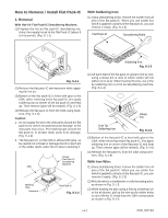
[7] Function CBA (S-5) [6] AV CBA CN2001 (S-6) (L-5) Fig. 6 HOW TO EJECT MANUALLY (Method 1) 1 Remove the Top Case. 2 Remove the Reinforce Plate. 3 Rotate the roulette in the direction of the arrow as shown below. View for A Rotate this roulette in the direction of the arrow A 1-6-3 E592ADC - Sharp DV-SL90UM | Service Manual - Page 14
HOW TO EJECT MANUALLY (Method 2) 1 Turn the unit over. 2 Insert the shaft less than a diameter of 3 mm (e.g. screwdriver) straightly into the opening as shown. 3 Turn the shaft along with - Sharp DV-SL90UM | Service Manual - Page 15
VERSION : E5****_****.ab5 Completed SUM : 7ABC (*3) EXIT: POWER Fig. a Version Up Mode Screen Fig. e Completed Program Mode Screen Fig. b VFD in Version Up Mode The DVD player can also enter the version up mode with the tray open. In this case, Fig. a will be shown on the screen while the tray - Sharp DV-SL90UM | Service Manual - Page 16
"*******" differ depending on the models. MODEL : ******* Version : *.** Region : * EEPROM CLEAR : OK EEPROM CLEAR : CLEAR EXIT: POWER Fig. h When "OK" appears on the screen, the factory default will be set. Then the firmware renewal mode is complete. 11.To exit this mode, press [POWER] button. - Sharp DV-SL90UM | Service Manual - Page 17
TROUBLESHOOTING FLOW CHART NO.1 The power cannot be turned on. Is the fuse ? Yes Is the EV +3.3V line voltage normal? No Yes Check each rectifying circuit of the secondary circuit and service it if defective. FLOW CHART NO.2 The fuse blows out. See FLOW CHART No.2 - Sharp DV-SL90UM | Service Manual - Page 18
outputted. (EV+11V is outputted normally.) Is the "H" signal inputted into the base of Q1004? No Yes Replace Q1004. Check R1068 and D1046, and service it if defective. FLOW CHART NO.8 P-ON+3.3V is not outputted. (P-ON+10V is outputted normally.) Is 3.3V voltage supplied to the collector of Q1011 - Sharp DV-SL90UM | Service Manual - Page 19
"L" pulse supplied to the Pin(22) of CN1001? Yes Replace DVD Main CBA. Check the EV+3.3V line and service it if defective. Check the -FL (-20V) line and service it if defective. Check R2002, IC2001 and their periphery, and service it if defective. Check D1016, D1017, T1001, and their periphery - Sharp DV-SL90UM | Service Manual - Page 20
is poor. FLOW CHART NO.17 [No Disc] indicated. (When the focus servo is not functioning.) Replace the DVD Main CBA. No improvement can be found. Yes Replace the DVD Mecha. No Original DVD Main CBA is poor. FLOW CHART NO.18 [No Disc] indicated. (When the laser beam does not light up - Sharp DV-SL90UM | Service Manual - Page 21
the composite video signals outputted to No the VIDEO OUT terminal (JK1404)? Replace the DVD Main CBA or DVD Mecha. Check the line between each pin of CN1601 and each pin of IC1402, IC1403 on the AV CBA, and service it if detective. CN1601 8PIN → IC1402 CN1601 6PIN → IC1402 CN1601 4PIN → IC1402 - Sharp DV-SL90UM | Service Manual - Page 22
No output terminal? Are the audio signals outputted to the audio terminal (JK1404)? Replace the DVD Main CBA or DVD Mecha. Check each line between each pin of CN1601 and each pin of IC1201 on AV CBA, and service it if detective. CN1601 14PIN → IC1201 2PIN AUDIO-L CN1601 16PIN → IC1201 6PIN AUDIO - Sharp DV-SL90UM | Service Manual - Page 23
22 143 SP-ROT 81 SL-AMP RM2001 REMOTE SENSOR K2 4 K1 3 SEGMENT CN2001 5 KEY-1 3 KEY-2 4 KEY-3 6 KEY-4 1 K2 2 K1 CN2101 5 3 4 6 1 2 KEY MATRIX 1-9-1 DRIVE CBA DVD MAIN CBA UNIT 66 TRAY-IN AV CBA FUNCTION CBA E592ABLS - Sharp DV-SL90UM | Service Manual - Page 24
DATA(VIDEO/AUDIO) SIGNAL VIDEO SIGNAL DATA(AUDIO) SIGNAL *Note: IC103 is not supplied separatery. Be sure to replace with the DVD Main CBA unit when servicing IC103. IC503 (SDRAM) SDRAM IC101 (MICRO CONTROLLER) ~~ 22 26 SDRAM ADDRESS(0-11) 217 SDRAM ADDRESS(0-11) ~ 29 238 35 EXTERNAL - Sharp DV-SL90UM | Service Manual - Page 25
DETECT 11 ADAC-MD ADAC-MC ADAC-ML 13 14 SERIAL 15 CONTROL TO SYSTEM CONTROL /SERVO BLOCK DIAGRAM SYSTEM CLOCK 16 PCM-SCLK A-MUTE DVD MAIN CBA UNIT WF6 CN601 19 SPDIF 14 AUDIO-L 16 AUDIO-R 15 A-R-MUTE 13 A-MUTE CN1601 19 14 16 15 13 Q1351 AMP IC1204 OPTICAL - Sharp DV-SL90UM | Service Manual - Page 26
Power Supply Block Diagram CAUTION ! Fixed voltage ( or Auto voltage selectable ) power supply circuit is used in this unit. If Main Fuse (F1001) is blown, check to see that all components in the power supply circuit are not defective before you connect the AC plug to the AC power supply. Otherwise - Sharp DV-SL90UM | Service Manual - Page 27
identified by the mark " # " in the schematic diagram and the parts list. Before replacing any of these components, read the parts list in this manual carefully. The use of substitute replacement parts that do not have the same safety characteristics as specified in the parts list may create shock - Sharp DV-SL90UM | Service Manual - Page 28
of repaired units, use only original replacement parts which are listed with their part numbers in the parts list section of the service manual. 4. Voltage indications for PLAY and STOP mode on the schematics are as shown below: 1 2 (Unit: Volt) 5.0 3 5.0 (2.5) PLAY mode STOP mode The same - Sharp DV-SL90UM | Service Manual - Page 29
DVD Main 1/3 Schematic Diagram 1-10-3 1-10-4 E592ASCD1 - Sharp DV-SL90UM | Service Manual - Page 30
DVD Main 2/3 Schematic Diagram 1-10-5 1-10-6 E592ASCD2 - Sharp DV-SL90UM | Service Manual - Page 31
IC101 VOLTAGE CHART PIN.NO PLAY STOP PIN.NO PLAY 1 ~ ~ 33 ~ 2 ~ ~ 34 3.4 3 0 0 35 0 4 ~ ~ 36 ~ 5 ~ ~ 37 ~ 6 3.4 3.4 38 0.4 7 ~ ~ 39 ~ 8 ~ ~ 40 ~ 9 0 0 41 ~ 10 ~ ~ 42 ~ 11 ~ ~ 43 ~ 12 3.4 3.4 44 1.3 13 ~ ~ 45 ~ 14 ~ ~ 46 ~ 15 ~ - Sharp DV-SL90UM | Service Manual - Page 32
DVD Main 3/3 Schematic Diagram * Note: IC103 is not supplied separately. Be sure to replace with the DVD Main CBA unit when servicing IC103. 1-10-9 1-10-10 E592ASCD3 - Sharp DV-SL90UM | Service Manual - Page 33
AV 1/3 Schematic Diagram CAUTION ! Fixed voltage ( or Auto voltage selectable ) power supply circuit is used in this unit. If Main Fuse (F1001) is blown, check to see that all components in the power supply circuit are not defective before you connect the AC plug to the AC power supply. Otherwise it - Sharp DV-SL90UM | Service Manual - Page 34
AV 2/3 Schematic Diagram 1-10-13 1-10-14 E592ASCAV2 - Sharp DV-SL90UM | Service Manual - Page 35
Diagram 7G 6G 5G 4G 3G 2G 1G VCR REPEAT TITLE GROUP AB ALL f i i REC SACD CHP TRK PSCAN a c b DVD A d PM f g e HD VCD FL2001 MATRIX CHART 7G 6G 5G 4G a a a a b REPEAT b b b cA c c c dB d d d e ALL e e e f f f f f g g g g h GROUP i i TITLE VCR 3G 2G - Sharp DV-SL90UM | Service Manual - Page 36
DVD MAIN CBA Top View 1-10-17 1-10-18 BE5900G04012 - Sharp DV-SL90UM | Service Manual - Page 37
DVD MAIN CBA Bottom View 1-10-19 1-10-20 BE5900G04012 - Sharp DV-SL90UM | Service Manual - Page 38
AV CBA Top View CAUTION ! Fixed voltage ( or Auto voltage selectable ) power supply circuit is used in this unit. If Main Fuse (F1001) is blown, check to see that all components in the power supply circuit are not defective before you connect the AC plug to the AC power supply. Otherwise it may - Sharp DV-SL90UM | Service Manual - Page 39
AV CBA Bottom View CAUTION ! Fixed voltage ( or Auto voltage selectable ) power supply circuit is used in this unit. If Main Fuse (F1001) is blown, check to see that all components in the power supply circuit are not defective before you connect the AC plug to the AC power supply. Otherwise it may - Sharp DV-SL90UM | Service Manual - Page 40
FUNCTION CBA Top View FUNCTION CBA Bottom View 1-10-25 1-10-26 BE5942F01011B - Sharp DV-SL90UM | Service Manual - Page 41
VIDEO-C 0.2V 20µs WF3 C1402 PLUS LEAD VIDEO-CVBS 0.5V 20µs WF4 Pin 14 of CN1601 SPDIF 1V 0.1µs NOTE: Input CD: 1kHz PLAY (WF4~WF6) DVD: POWER ON (STOP) MODE (WF1~WF3) AUDIO-L 1V 0.5ms 1-11 -1 E5945WF - Sharp DV-SL90UM | Service Manual - Page 42
20 FP-STB 20 21 FP-DOUT 21 22 REMOTE 22 CN401 CN301 SL(+) 8 SL(-) 7 GND 6 TRAY-IN 5 SP(-) 4 SP(+) 3 1-12-1 SLED MOTOR M SPINDLE MOTOR M DVD MECHA TRAY-IN DRIVE CBA FS TS 7 9 11 2 3 6 5 4 DETECTOR PICK UP UNIT E592AWI OUT OUT OUT VIDEO-Y VIDEO-Cb/Pb VIDEO-Cr/Pr VIDEO OUT - Sharp DV-SL90UM | Service Manual - Page 43
SYSTEM CONTROL TIMING CHARTS Tray Close ~ Play / Play ~ Tray Open Tray IN (TL221) 3.3V 0V Tray Close Sled Drive (TP303) 1.65V 0V Disc Drive (TP301) 1.65V 0V Focus Drive (TP304) 1.65V 0V Tracking Drive 1.65V (TP302) 0V Disc Rotation Play Disc Tray Stop Open 1-13-1 E5945TI - Sharp DV-SL90UM | Service Manual - Page 44
IC PIN FUNCTION DESCRIPTIONS IC2001 ( PT6313-S -TP ) Pin No. In/Out Signal Name Name Function 1 In FP-CLK Clock Input 2 In FP-STB Serial Interface Strobe 3 In K1 Key Data 1 Input 4 In K2 Key Data 2 Input 5 - VSS GND 6 - VDD Power Supply 7 Out a / KEY-1 Segment Output / Key Souce-1 - Sharp DV-SL90UM | Service Manual - Page 45
LEAD IDENTIFICATIONS KTC3203(Y) E C B KTA1266(Y) KRA110M KTA1267(Y) KTC3199(GR,Y) PQ070XZ5MZP 3 12345 1: Vin 2: Vc 3: Vo 4: Vadj 5: GND E C B MM1636XWRE 8 5 KIA4558P 8 5 PT6313-S-TP 28 15 KIA431-AT 1 4 1 4 1 14 MM1637XVBE 16 9 1 8 2SK3566 G D S LTV-817B-F A C K A R K - Sharp DV-SL90UM | Service Manual - Page 46
this mark. Some Ref. Numbers are not in sequence. 2L081 2B5 2L081 2L011 2L011 2L011 A2 2L021 2L021 2L021 Function CBA A16 2L021 1B1 2L105 DVD Main CBA Unit 2L105 2L031 JK1401 JK1404 JK1202 F1001 AV CBA 2B1 A21 IC1204 2B11 2L042 AC1001 2L041 A13 A1X A13 A15 1-16-1 E592AEX - Sharp DV-SL90UM | Service Manual - Page 47
Packing S2 X10 X1 X5 X2 X4 S2 S4 Unit A22 S1 1-16-2 E592AEX - Sharp DV-SL90UM | Service Manual - Page 48
, read carefully the product safety notice in this service manual. Don't degrade the safety of the product through improper servicing. Ref. No. A1X A2 A13 A15 A16 A21 E5500UD REMOTE CONTROL UNIT DVD 0842 VCZF05EE DRY BATTERY R6P/2S ACCESSORY BAG E5700UD AV CORD OWNER'S MANUAL E592AZD Part No. - Sharp DV-SL90UM | Service Manual - Page 49
manual. Don't degrade the safety of the product through improper servicing. NOTES: 1. Parts that not assigned part numbers are not available. 2. IC103 is not supplied separately. Be sure to replace with the DVD Main CBA unit when servicing IC103. 3. Tolerance of Capacitors and Resistors are - Sharp DV-SL90UM | Service Manual - Page 50
Ref. No. C212 C215 C217 C218 C219 C220 C221 C222 C223 C224 C225 C226 C227 C228 C229 C230 C231 C232 C233 C234 C237 C238 C239 C250 C253 C255 C257 C259 C263 C280 C281 C284 C288 C289 C301 C302 C303 C305 C308 C310 C311 C313 C314 C315 C316 C317 C318 C324 C325 C326 C327 C328 C329 C402 C403 C405 C410 C411 - Sharp DV-SL90UM | Service Manual - Page 51
6P 04 6232 106 102 800 FFC/FPC CONNECTOR 22P 04 6232 122 102 800 FFC CONNECTOR 17P 9611S-17Y914 SWITCHING DIODE DAN202U T106 DVD 1CHIP LSI MN35202 16M MIRROR FLASH MOMORY MBM29LV160BM90TN 1CIRCUIT ANALOG SWITCH NC7SB3157P6X OPAMP LM324PWR ACTUATER DRIVER SA5694 IC:RESET IC-PST3229NR SYSTEM RESET IC - Sharp DV-SL90UM | Service Manual - Page 52
Ref. No. L501 L561 L611 L612 L613 L614 L617 L618 TRANSISTORS Q251 Q252 Q253 Q254 RESISTORS R101 R102 R106 R107 R108 R109 R110 R112 R113 R114 R116 R120 R121 R122 R124 R128 R131 R133 R191 R192 R203 R206 R208 R213 R214 R217 R218 R219 R220 R225 R226 R227 R228 R231 R232 R233 R234 R241 R242 R243 R251 R252 - Sharp DV-SL90UM | Service Manual - Page 53
Ref. No. R279 R280 R281 R282 R283 R284 R285 R286 R289 R298 R299 R301 R302 R303 R304 R305 R306 R307 R308 R313 R315 R316 R317 R318 R319 R320 R321 R322 R325 R333 R334 R402 R403 R404 R405 R406 R407 R413 R415 R417 R421 R422 R423 R471 R509 R510 R562 R565 R567 R601 R607 R610 R618 R619 MISCELLANEOUS X101 - Sharp DV-SL90UM | Service Manual - Page 54
AV CBA + FUNCTION CBA Ref. No. AV CBA + FUNCTION CBA Consists of the following AV CBA FUNCTION CBA Description AV CBA Ref. No. CAPACITORS C1001# C1003 C1004 C1005 C1006# C1007 C1009 C1010 C1013 C1014 C1017 C1018 C1021 C1022 C1029 C1032 C1033 C1034 C1035 C1036 C1037 C1038 C1039 C1047 C1048 C1049 - Sharp DV-SL90UM | Service Manual - Page 55
PHOTOCOUPLER LTV-817B-F VOLTAGE REGULATOR PQ070XZ5MZP IC:SHUNT REGULATOR KIA431-AT IC:OP AMP KIA4558P FIBER OPTIC TRANS.MODULE 0C-0805T*002 DRIVER FOR DVD MM1637XVBE DRIVER FOR DVD MM1636XWRE FL DRIVER IC PT6313-S-TP LINE FILTER 50MH LF-4Z-E503 CHOKE COIL 22µH-K PCB JUMPER D0.6-P5.0 1-18-7 Part No - Sharp DV-SL90UM | Service Manual - Page 56
Ref. No. L1009 L1011 L1060 L1350 L1351 L1401 L1421 L1441 L1442 L1461 L1481 L1521 L1522 L2001 L2031 TRANSISTORS Q1001 Q1002 Q1003 Q1004 Q1005 Q1008 Q1011 Q1015 Q1016 Q1201 Q1202 Q1204 Q1351 Q1352 RESISTORS R1002 R1004 R1005 R1006 R1008 R1010 R1011 R1013 R1014 R1015 R1016 R1019 R1020 R1021 R1022 R1023 - Sharp DV-SL90UM | Service Manual - Page 57
Ref. No. R1079 R1080 R1081 R1082 R1083 R1084 R1085 R1091 R1092 R1095 R1097 R1205 R1206 R1207 R1208 R1209 R1210 R1211 R1212 R1221 R1222 R1223 R1224 R1225 R1226 R1227 R1228 R1236 R1238 R1240 R1245 R1351 R1352 R1353 R1354 R1355 R1356 R1366 R1392 R1396 R1397 R1402 R1403 R1421 R1422 R1441 R1442 R1443 - Sharp DV-SL90UM | Service Manual - Page 58
Ref. No. 2L042 2B1 2B11 AC1001# F1001# FL2001 FH1001 FH1002 J1423 J2009 J2647 JK1202 JK1401 JK1404 RM2001 SA1001# T1001 W1006 Description SCREW, S-TIGHT M3X8 BIND HEAD+ HOLDER, F.I.P. E5900UD HEATSINK E5717QD AC CORD PE8B2F51H0AA067 FUSE T1.6AL/250V V.F.D. 7-BT-298N FUSE HOLDER MSF-015 FUSE HOLDER - Sharp DV-SL90UM | Service Manual - Page 59
DV-SL90UM COPYRIGHT © 2004 BY SHARP CORPORATION ALL RIGHTS RESERVED. No part of this publication may be reproduced without prior written permission of the publisher. Jul. 2004 Printed in JAPAN SHARP CORPORATION AV Systems Group Quality & Reliability Control Center Yaita, Tochigi 329-2193, Japan 1
-
 1
1 -
 2
2 -
 3
3 -
 4
4 -
 5
5 -
 6
6 -
 7
7 -
8
-
9
-
10
-
11
-
12
-
13
-
14
-
15
-
16
-
17
-
18
-
19
-
20
-
21
-
22
-
23
-
24
-
25
-
26
-
27
-
28
-
29
-
30
-
31
-
32
-
33
-
34
-
35
-
36
-
37
-
38
-
39
-
40
-
41
-
42
-
43
-
44
-
45
-
46
-
47
-
48
-
49
-
50
-
51
-
52
-
53
-
54
-
55
-
56
-
57
-
58
-
59
 |
 |
DV-SL90UM
S64U2DV-SL90U
SERVICE MANUAL
In the interests of user-safety (Required by safety
regulations in some countries) the set should be
restored to its original condition and only parts
identical to those specified be used.
MODEL
SERVICE MANUAL
DVD VIDEO PLAYER
MODEL
DV-SL90UM
DVD VIDEO PLAYER
This document has been published to be used for
after sales service only.
The contents are subject to change without notice.
SHARP CORPORATION
DV-SL90UM
Page
SPECIFICATIONS
.............................................................................................................................
1-1-1
LASER BEAM SAFETY PRECAUTIONS
..........................................................................................
1-2-1
IMPORTANT SAFEGUARDS AND PRECAUTIONS
.........................................................................
1-3-1
STANDARD NOTES FOR SERVICING
.............................................................................................
1-4-1
OPERATING CONTROLS AND FUNCTIONS
..................................................................................
1-5-1
CABINET DISASSEMBLY INSTRUCTIONS
.....................................................................................
1-6-1
FIRMWARE RENEWAL MODE
.........................................................................................................
1-7-1
TROUBLESHOOTING
.......................................................................................................................
1-8-1
BLOCK DIAGRAMS
...........................................................................................................................
1-9-1
SCHEMATIC DIAGRAMS/ CBA’S AND TEST POINTS
..................................................................
1-10-1
WAVEFORMS
..................................................................................................................................
1-11-1
WIRING DIAGRAM
..........................................................................................................................
1-12-1
SYSTEM CONTROL TIMING CHARTS
..........................................................................................
1-13-1
IC PIN FUNCTION DESCRIPTIONS
...............................................................................................
1-14-1
LEAD IDENTIFICATIONS
................................................................................................................
1-15-1
EXPLODED VIEWS
.........................................................................................................................
1-16-1
MECHANICAL PARTS LIST
............................................................................................................
1-17-1
ELECTRICAL PARTS LIST
.............................................................................................................
1-18-1
CONTENTS
4