Sharp KB-4425J Installation Manual - Page 4
Electrical Connections
 |
View all Sharp KB-4425J manuals
Add to My Manuals
Save this manual to your list of manuals |
Page 4 highlights
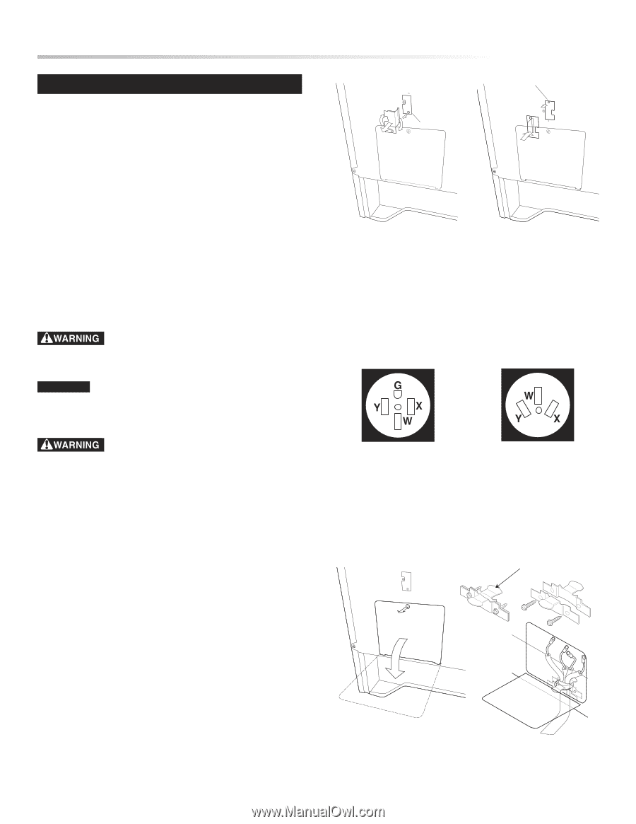
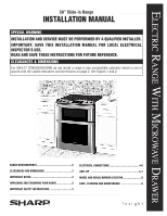
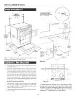
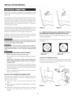
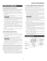
INSTALLATION MANUAL ELECTRICAL CONNECTIONS The installer or consumer is responsible for connecting the power supply cord to the connection block located behind the back panel access cover. This range may be connected by means of permanent "hard wiring" (flexible armored or nonmetallic shielded copper or aluminum cable), or by means of a power supply cord kit. Only a power supply cord kit rated at 240 volts or 208 volts and 50 amperes and marked for use with ranges shall be used. Cord must have either 3 or 4 conductors to match electric receptacle. For mobile homes, new installations, recreational vehicles or areas where local codes do not permit grounding through neutral, a 4 conductor power supply cord kit rated at 240 volts or 208 volts minimum, 50 amperes and marked for use with ranges should be used. Terminals on end of wires must be either closed loop or open-end spade lugs with upturned ends. Cord must have strain-relief clamp. The range connection opening should be 1 3/8-inches. Risk of fire or electrical shock exists if an incorrect size range cord kit is used or the Installation Manual or strain relief clamp are disregarded. CAUTION Do not loosen the nuts which secure the factoryinstalled range wiring to the terminal block while connecting range. Electrical failure or loss of electrical connection may occur. ELECTRICAL SHOCK HAZARD • Electrical ground is required on this range. • Do not connect to the electrical supply until range is permanently grounded. • DISCONNECT POWER TO THE CIRCUIT BREAKER OR FUSE BOX BEFORE MAKING THE ELECTRICAL CONNECTION. • This range must be connected to a grounded, metallic, permanent wiring system or the grounding connector of the power cord should be connected to the grounding terminal or wire lead on the range. • Failure to heed these warnings could result in a fire, personal injury or electrical shock. 208/240 VOLT CONNECTION INSTRUCTIONS The range can be set for 208V or 240V. The voltage setting for your range is pre-set at 240V from the factory. Follow these steps to change the voltage setting. 1 Locate the voltage switch on the lower back side of the range. 2 Remove the screw and rotate the switch plate 180˚ as indicated in the Figure 4. 3 Reinsert the switch plate and replace screw as indicated in Figure 5. The voltage setting is indicated by the visible marking. 180˚ screw 240V 208V screw Figure 4 screw Figure 5 208V 3 & 4-WIRE ELECTRICAL WALL RECEPTACLE TYPES & RECOMMENDED MOUNTING ORIENTATION ON WALL Figure 6A illustrates 4-wire receptacle required for new and remodeled installations. Figure 6B illustrates 3-wire receptacle that is allowed for existing installations. 4-wire wall receptacle (14-50R) 4-wire wall receptacle (14-50R) Figure 6A 3-wire wall receptacle (10-50R) Figure 6B ACCESS TO TERMINAL BLOCK Loosen screw on rear access cover and pull down as illustrated in Figure 7 to access terminal block wiring connection. To close, return to original location and secure screw. strain relief clamp 3-wire wall receptacle (10-50R) strain relief clamp Figure 7 Figure 8 4
-
 1
1 -
 2
2 -
 3
3 -
 4
4 -
 5
5 -
 6
6 -
 7
7 -
 8
8
 |
 |