Sharp KB-4425J Installation Manual - Page 7
Installation Manual
 |
View all Sharp KB-4425J manuals
Add to My Manuals
Save this manual to your list of manuals |
Page 7 highlights
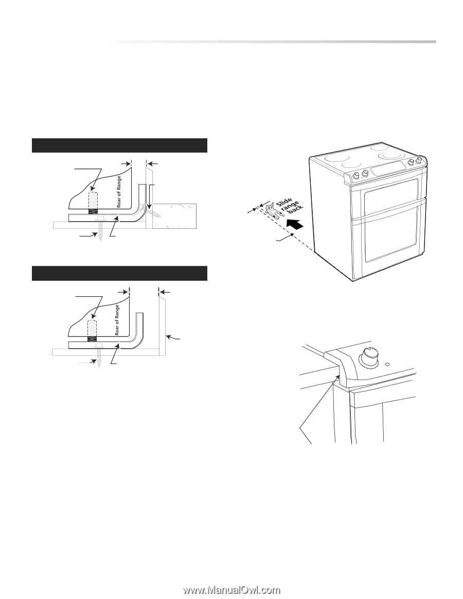
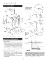
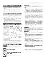
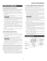
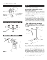
2 DRILL PILOT HOLES AND FASTEN BRACKET Drill a 1/8-inch pilot hole where screws are to be located. If bracket is to be mounted to the wall, drill pilot hole at an approximate 20 degree downward angle. If bracket is to be mounted to masonry or ceramic floors, drill a 5/32-inch pilot hole 1 3/4-inches deep. The screws provided may be used in wood or concrete material. Use a 5/16-inch nut-driver or flat head screwdriver to secure the bracket in place. FASTEN BRACKET (WALL OR FLOOR MOUNTING) leveling leg max 1 1/4" wall mount INSTALLATION MANUAL 3 LEVEL AND POSITION RANGE Level range by adjusting the (4) leveling legs with a wrench. Note: A minimum clearance of 1/8-inch is required between the bottom of the range and the leveling leg to allow room for the bracket. Use a level to check your adjustments. Plug range into properly prepared electrical receptacle or if hard wired, check that it was completed properly. Check floor condition for evenness and stability. Slide range back into position. floor mount Figure 14 wall plate Anti-Tip bracket FASTEN BRACKET (FLOOR MOUNTING ONLY) leveling leg more than 1 1/4" floor mount Figure 15 wall Anti-Tip bracket 1 5/8" Range Slide Figure 16 Visually check that rear leveling leg is inserted into and fully secured by the Anti-Tip bracket by looking underneath the range with a flashlight and carefully attempt to tilt it forward. Figure 17 Slide range in cabinet until control panel edge is flush with the countertop front edge. 7
-
 1
1 -
 2
2 -
 3
3 -
 4
4 -
 5
5 -
 6
6 -
 7
7 -
 8
8
 |
 |