Sharp LC-15AV7U Service Manual - Page 25
FLOW CHART NO.19, SW1103, SW1111 do
 |
View all Sharp LC-15AV7U manuals
Add to My Manuals
Save this manual to your list of manuals |
Page 25 highlights
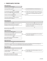
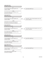
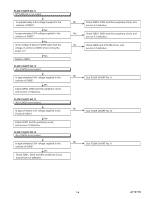
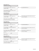
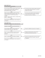
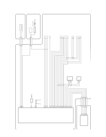
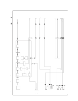
FLOW CHART NO.19 The key operation is not functioning. No Are the contact point and installation state of the key switches (SW1101,SW1102,SW1103,SW1104, SW1105,SW1107,SW1111) normal? Yes When pressing each switches (SW1101,SW1102, SW1103,SW1104,SW1105,SW1107,SW1111) do the No voltage of each pin of CN102A (shown below) increase? SW1101,1102,1103,1104,1105,1107 : CN1301 PIN 2 SW1111 : CN1301 PIN 1 Yes Check IC1202 and the periphery circuit, and service it if defective. FLOW CHART NO.20 No operation is possible from the remote control unit. Operation is possible from the remote control unit. Yes Is 3.3V voltage supplied to Pin(3) terminal of the No infrared remote control receiver (RCV1142)? Yes Is the "L" pulse sent out Pin(1) terminal of receiver No (RCV1142) when the infrared remote control is activated? Yes Is the "L" pulse supplied to the Pin(3) of CN1302? No Yes Check IC1202 and the periphery circuit, and service it if defective. Re-install the switches (SW1101,SW1102,SW1103, SW1104,SW1105,SW1107,SW1111) correctly or replace the poor switch. Check the switches (SW1101,SW1102,SW1103, SW1104,SW1105,SW1107,SW1111) and their periphery, and service it if defective. Check AL+3.3V(D) line and service it if defective. Replace the infrared remote control receiver (RCV1142) or the remote control unit. Check the line between Pin(1) terminal of receiver (RCV1142) and Pin(3) of CN1302 , and service it if defective. 7-6 A7121TS
-
 1
1 -
2
-
3
-
4
-
5
-
6
-
7
-
8
-
9
-
10
-
11
-
12
-
13
-
14
-
15
-
16
-
17
-
18
-
19
-
 20
20 -
 21
21 -
 22
22 -
 23
23 -
 24
24 -
 25
25 -
 26
26 -
 27
27 -
 28
28 -
 29
29 -
 30
30 -
31
-
32
-
33
-
34
-
35
-
36
-
37
-
38
-
39
-
40
-
41
-
42
-
43
-
44
-
45
-
46
-
47
-
48
-
49
-
50
-
51
-
52
-
53
-
54
-
55
-
56
-
57
-
58
-
59
-
60
-
61
-
62
-
63
-
64
-
65
-
66
-
67
-
68
-
69
-
70
-
71
-
72
-
73
 |
 |
