Sharp PN-UH601 PN-UH601 PN-UH701 Operation Manual - Page 80
Appendix - specs
 |
View all Sharp PN-UH601 manuals
Add to My Manuals
Save this manual to your list of manuals |
Page 80 highlights
sharp operation manual >> Appendix
-
 1
1 -
2
-
3
-
4
-
5
-
6
-
7
-
8
-
9
-
10
-
11
-
12
-
13
-
14
-
15
-
16
-
17
-
18
-
19
-
20
-
21
-
22
-
23
-
24
-
25
-
26
-
27
-
28
-
29
-
30
-
31
-
32
-
33
-
34
-
35
-
36
-
37
-
38
-
39
-
40
-
41
-
42
-
43
-
44
-
45
-
46
-
47
-
48
-
49
-
50
-
51
-
52
-
53
-
54
-
55
-
56
-
57
-
58
-
59
-
60
-
61
-
62
-
63
-
64
-
65
-
66
-
67
-
68
-
69
-
70
-
71
-
72
-
73
-
74
-
 75
75 -
 76
76 -
 77
77 -
 78
78 -
 79
79 -
 80
80 -
 81
81 -
 82
82 -
 83
83 -
 84
84 -
 85
85 -
86
-
87
-
88
-
89
-
90
-
91
-
92
-
93
-
94
-
95
-
96
-
97
 |
 |
sharp operation manual
file:///Y|/11_IM%20GROUP/Oversea%20Group/SHARP%20JAPAN/JC180020_PN-UH601_PN-UH701_HTML/HTML/eng/9-1.html[2/28/2018 7:09:02 PM]
>>
<<
Appendix
ENG 9-1
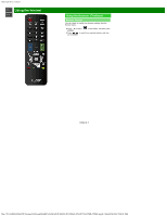
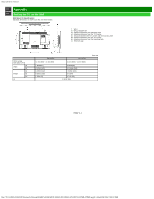
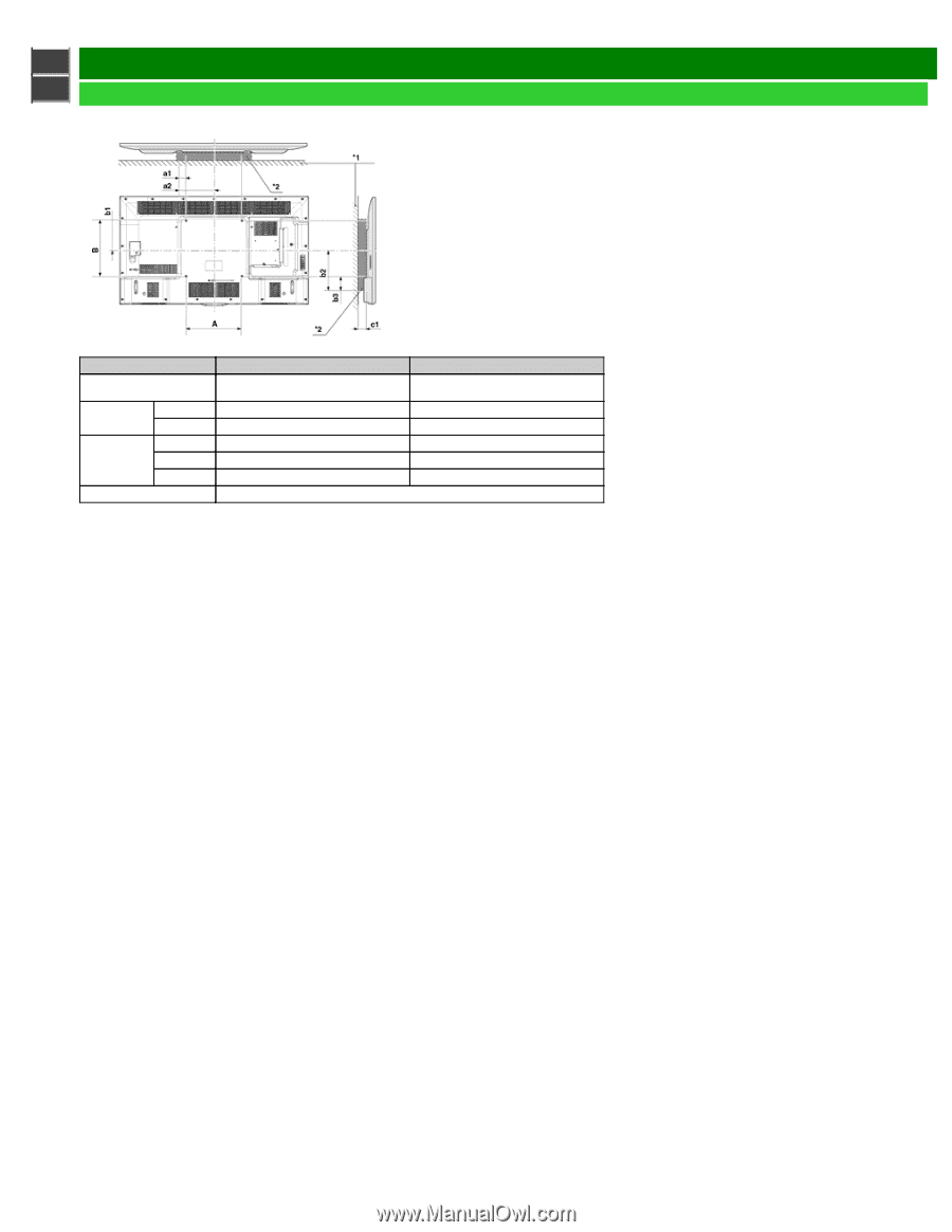
Setting the TV on the Wall
Wall Mount Kit Specifications
Standard dimensions for wall mount kits are shown below.
PN-UH601
PN-UH701
VESA screw
hole specs (A-B)
15 3/4 (400) - 15 3/4 (400)
15 3/4 (400) - 15 3/4 (400)
Width
a1
1 55/64(47)
3 23/64(85)
a2
9 47/64 (247)
11 15/64 (285)
Height
b1
8 23/64 (212)
7 61/64 (202)
b2
8 15/32 (215)
10 (254)
b3
1 5/64 (27)
2 7/32 (56)
c1
1 31/32 (50)
Unit: mm
*1 : WALL
*2 : WALL MOUNT KIT
a1 : Maximum distance from mounting hole.
a2 : Maximum distance from the TV’s center.
b1 : Distance between the TV’s center and the mounting hole.
b2 : Maximum distance from the TV’s center.
b3 : Maximum distance from the mounting hole.
c1 : Minimum gap.