Sharp R530EST Operation Manual - Page 6
Installation Instructions - dimensions
 |
UPC - 074000639652
View all Sharp R530EST manuals
Add to My Manuals
Save this manual to your list of manuals |
Page 6 highlights
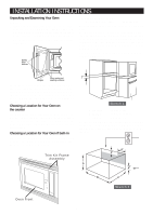
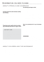
INSTALLATION INSTRUCTIONS Unpacking and Examining Your Oven Remove: 1. all packing materials from inside the oven cavity; however, DO NOT REMOVE THE WAVEGUIDE COVER, which is located on the right cavity wall. Read enclosures and SAVE the Operation Manual. 2. the feature sticker, if there is one, from the outside of the door. The applicable wall oven is: General Electric (27") ZET837SYSS Do not build-in above any other gas or electric wall oven. See Sketch 1 for proper location when building in above the specified wall oven. Carefully follow both the wall oven installation instructions and Sharp's Built-in Kit instructions. Be sure that the clearance of the floor between the wall oven and the microwave oven is minimum of 2 inches. The opening in the wall or cabinet must be within the following dimensions: 2" Check the oven for any damage, such as misaligned or bent door, damaged door seals and sealing surfaces, broken or loose door hinges and latches and dents inside the cavity or on the door. If there is any damage, do not operate the oven and contact your dealer or SHARP AUTHORIZED SERVICER. Choosing a Location for Your Oven on the counter You will use the oven frequently so plan its location for ease of use. It's wise, if possible, to have counter space on at least one side of the oven. Allow at least 2 inches on the sides, top and at the rear of the oven for air circulation. Choosing a Location for Your Oven if built-in Your oven can be built into a cabinet or wall by itself or above the wall oven listed in next column. The RK-51S27 is for the 27" wall oven. Trim Kit Frame Assembly Sketch 1 A HEIGHT B WIDTH C DEPTH : 16 3/4" to 17" : 24 3/8" to 24 11/16" : minimum 20" Outlet should NOT be in the shaded area as indicated on Sketch 2. If the dimension of DEPTH (C) is more than 21", the outlet location may be any area on the rear wall. 6" 4" A 4" B C Sketch 2 Oven Front 4
-
 1
1 -
 2
2 -
 3
3 -
 4
4 -
 5
5 -
 6
6 -
 7
7 -
 8
8 -
 9
9 -
 10
10 -
 11
11 -
 12
12 -
13
-
14
-
15
-
16
-
17
-
18
-
19
-
20
-
21
-
22
-
23
-
24
-
25
-
26
-
27
-
28
-
29
-
30
-
31
-
32
-
33
-
34
-
35
-
36
-
37
-
38
-
39
-
40
 |
 |
