Sharp XL-ES5 XL-ES5 XL-ES50 Operation Manual - Page 11
Preparation for Use
 |
View all Sharp XL-ES5 manuals
Add to My Manuals
Save this manual to your list of manuals |
Page 11 highlights
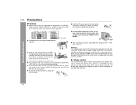
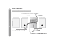
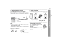
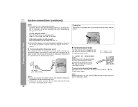
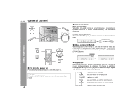
„ FM/AM loop antenna connection Connect the FM/AM loop antenna to the ANTENNA jack. Position the FM antenna wire and rotate the AM loop antenna for optimum reception. Place the AM loop antenna on a shelf, or attach it to a stand or a wall. „ Speaker connection Connect the black wire to the minus (-) terminal, and the red wire to the plus (+) terminal. Front speaker Subwoofer (right) Front speaker (left) XL-ES5 XL-ES50 Preparation for Use Notes: z Placing the antenna on the stereo system or near the AC power cord may cause noise pickup. Place the antenna away from the stereo system for better reception. z Do not connect the attached FM antenna to an external antenna as this may cause trouble. Installing the AM loop antenna: < Assembling > < Attaching to the wall > Red Black Caution: z Use speakers with an impedance of 6 ohms or more, as lower impedance speakers can damage the unit. z Do not mistake the right and the left channels. The right speaker is the one on the right side when you face the unit. z Do not let the bare speaker wires touch each other. z Do not allow any objects to fall into or to be placed in the bass reflex ducts. z Do not stand or sit on the speakers. You may be injured. Incorrect Wall Screws (not supplied) 11
-
 1
1 -
2
-
3
-
4
-
5
-
 6
6 -
 7
7 -
 8
8 -
 9
9 -
 10
10 -
 11
11 -
 12
12 -
 13
13 -
 14
14 -
 15
15 -
 16
16 -
17
-
18
-
19
-
20
-
21
-
22
-
23
-
24
-
25
-
26
-
27
-
28
-
29
-
30
-
31
 |
 |
