Sharp XR-41X Service Manual - Page 12
Calling and quitting the process mode with the control keys on this model. - locked
 |
View all Sharp XR-41X manuals
Add to My Manuals
Save this manual to your list of manuals |
Page 12 highlights
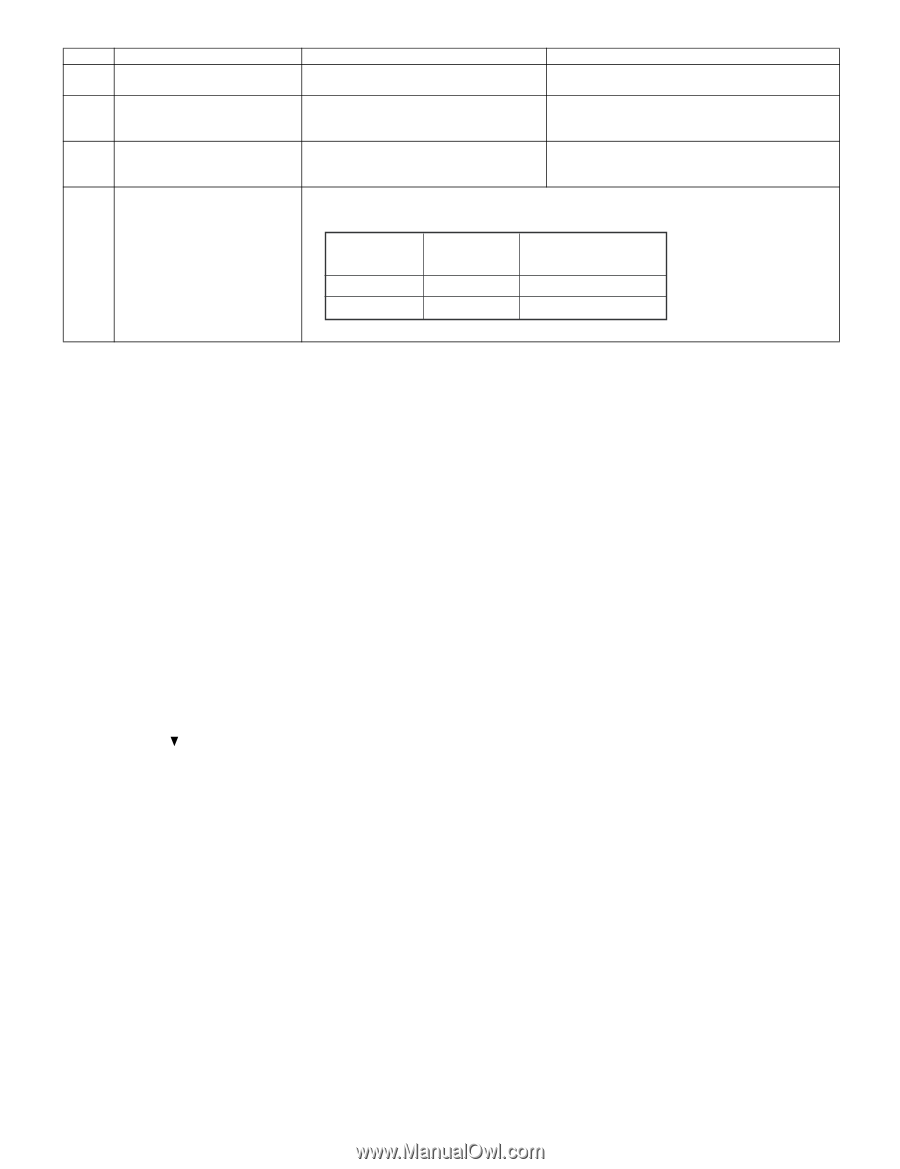
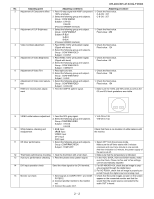
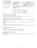
XR-40X/XR-41X/XG-F260X No. Adjusting point 16 RS232C operation check 17 Model name and version check 18 Setup guide screen check 19 Delivery settings Adjusting conditions 1. Connect the unit and a PC with the RS232C cable. 1. Select the following group. Group : INFO/VERSION. 1. Turn on the power after making the setup guide display ON setting or factory setting (SS4, etc.). 1. Make the following settings. Adjusting procedure 1. Send a command from the PC, and check it func- tions correctly. 1. The model name appears in the MODEL field, and the firmware version in the VERSION field. Check that they are correct. 1. Check that the 4-split screen is displayed correctly and the display contents are correct. Destination USA Others Process adjustment SS4 SS3 Remote control adjustment Factory setting at 4 Factory setting at 3 * Writing a software program (before main PWB is mounted) Use the DLP Composer Lite Ver. 4.2 to download the firmware. After writing the specified version of firmware to the PWB using the RS232C cable, check the version of the written firmware. If no software program is written, all three LEDs light up in the chassis inspection process. Calling and quitting the process mode with the control keys on this model. * Although it is possible for the process OUT to exit using the process menu, the IN/OUT toggle command is also available considering the existing specification. 1) Calling and quitting With the menu not displayed, press the "ENTER", "ENTER", "VOL+", "VOL-", "ENTER", "ENTER" and "MENU" keys on the remote control or on the main unit. 2) Others Press the S2551 process key (toggle) on the main PWB to call and quit the process menu. NOTE: When adjusting in the process mode, set a signal with a vertical frequency of 60 Hz or no signal. (May not be properly adjusted with other signals.) Resetting the lamp timer for this model 1) Resetting procedure In Stand-by, run this command to clear the operating time of the lamp to 0 and turn on the power. Press and hold " ", "ENTER", and "MENU", and then press the "STANDBY/ON" key of the set. Forced disabling of the System-Lock of this model 1) Disabling procedure With System-Lock input window onscreen, press the "MENU", "ENTER", "ENTER", "MENU", "ENTER", "ENTER" and "MENU" keys, in this order, on the remote controller. 2 - 3
-
 1
1 -
2
-
3
-
4
-
5
-
6
-
 7
7 -
 8
8 -
 9
9 -
 10
10 -
 11
11 -
 12
12 -
 13
13 -
 14
14 -
 15
15 -
 16
16 -
 17
17 -
18
-
19
-
20
-
21
-
22
-
23
-
24
 |
 |