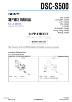
Sony DSC S500 Service Manual - Page 12
MAIN FRAME BLOCK, Stroboscope Block Assy Note 2 - replacement parts
 |
UPC - 027242692541
View all Sony DSC S500 manuals
Add to My Manuals
Save this manual to your list of manuals |
Page 12 highlights
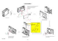
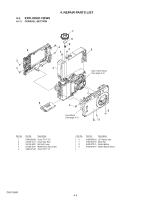
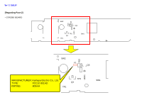
4. REPAIR PARTS LIST 4-1-3. MAIN FRAME BLOCK ns: not supplied 104 101 (Note 2) 107 106 103 (Note 2) 105 ns ns (Note 1) ns (Note 1) 105 102 ns (Note 1) Ref. No. 101 102 103 104 Part No. Description A-1205-305-A Stroboscope Block Assy (Note 2) 2-699-484-01 Holder, LCD A-1209-107-A TFT-LCD (Note 2) A-1209-106-A PC Board, Switch (Note 1) In case of the lens assembly, main board, or main frame assembly failure, contact your local Sony Service Headquarter for the measures. (Note 2) The adjustment is not required after replacing the stroboscope block assembly or LCD. Ref. No. 105 106 107 Part No. Description 2-682-983-01 Screw TP1.7*20 2-682-993-01 Sheet, Microphone Fixed A-1188-556-A Microphone Assy DSC-S500 4-3
-
 1
1 -
2
-
3
-
4
-
5
-
6
-
 7
7 -
 8
8 -
 9
9 -
 10
10 -
 11
11 -
 12
12 -
 13
13 -
 14
14 -
 15
15 -
 16
16 -
 17
17 -
18
 |
 |

4-3
DSC-S500
105
2-682-983-01
Screw TP1.7*20
106
2-682-993-01
Sheet, Microphone Fixed
107
A-1188-556-A
Microphone Assy
4-1-3.
MAIN FRAME BLOCK
(Note 1)
In case of the lens assembly, main board, or main frame
assembly failure, contact your local Sony Service
Headquarter for the measures.
4. REPAIR PARTS LIST
Ref. No.
Part No.
Description
Ref. No.
Part No.
Description
101
A-1205-305-A
Stroboscope Block Assy (Note 2)
102
2-699-484-01
Holder, LCD
103
A-1209-107-A
TFT-LCD (Note 2)
104
A-1209-106-A
PC Board, Switch
ns: not supplied
(Note 2)
The adjustment is not required after replacing the strobo-
scope block assembly or LCD.
105
102
104
103
(Note 2)
ns
ns
(Note 1)
101
(Note 2)
105
106
107
ns
(Note 1)
ns
(Note 1)