Sony DSC S500 Service Manual - Page 7
Caution, Shorting jig
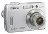 |
UPC - 027242692541
View all Sony DSC S500 manuals
Add to My Manuals
Save this manual to your list of manuals |
Page 7 highlights
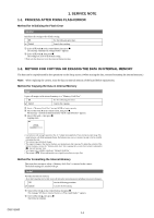
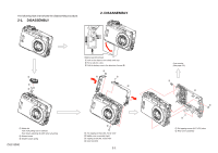
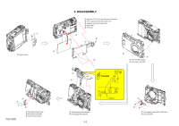
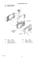
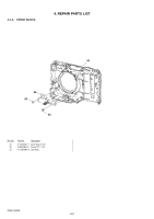
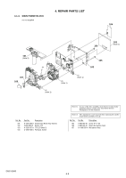
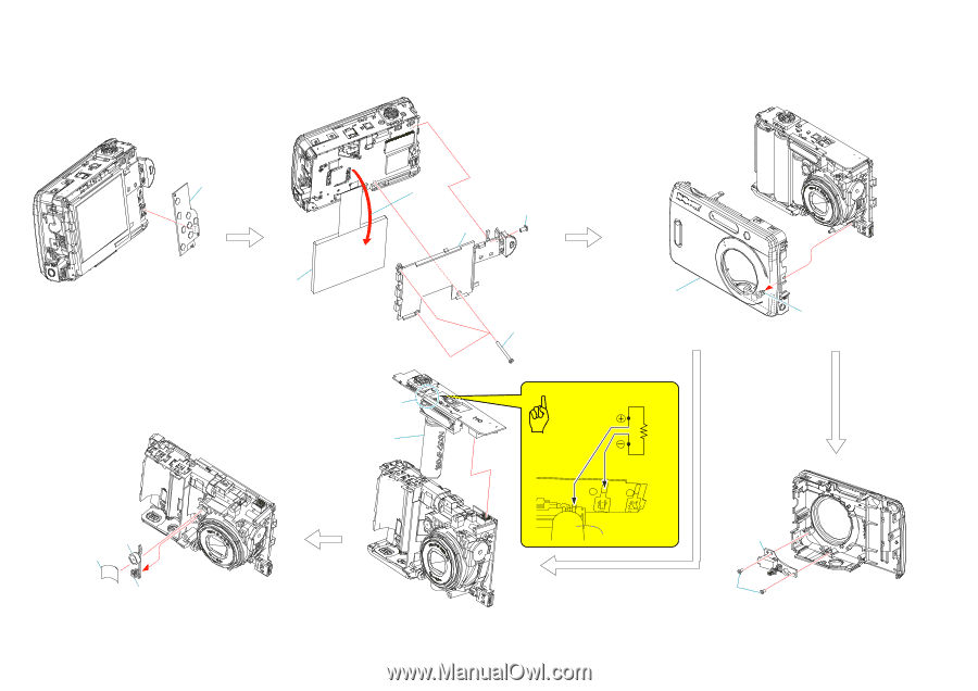
1 5 1 Switch board 2. DISASSEMBLY 1 Open the TFT-LCD in the direction of the arrow. 2 Three tapping screws (M1.7x20) silver 3 Tapping screw (M1.7x3.5) silver 4 LCD holder 5 TFT-LCD 1 3 4 2 1 2 1 From the MCU board 2 Front cover assembly Shorting jig 2 (1kΩ / 1W) Caution 1 2 1 DSC-S500 3 1 Microphone fixed sheet 2 Microphone assembly 3 From the MCU board 1 Stroboscope block assembly 2 Discharging the capacitor 2-2 Capacitor 2 1 1 Two tapping screws (M1.7x3.5) silver 2 Jack assembly
-
 1
1 -
 2
2 -
 3
3 -
 4
4 -
 5
5 -
 6
6 -
 7
7 -
 8
8 -
 9
9 -
 10
10 -
 11
11 -
 12
12 -
13
-
14
-
15
-
16
-
17
-
18
 |
 |
2-2
DSC-S500
2. DISASSEMBLY
Capacitor
Caution
Shorting jig
(1k
Ω
/ 1W)
1
Microphone fixed sheet
2
Microphone assembly
3
From the MCU board
1
Open the TFT-LCD in the direction of the arrow.
2
Three tapping screws (M1.7x20) silver
3
Tapping screw (M1.7x3.5) silver
4
LCD holder
5
TFT-LCD
1
From the MCU board
2
Front cover assembly
1
Two tapping screws (M1.7x3.5) silver
2
Jack assembly
1
Stroboscope block assembly
2
Discharging the capacitor
1
Switch board
1
5
4
2
1
2
3
1
2
1
1
2
3
1
2