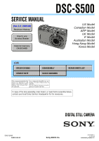
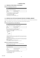
Sony DSC S500 Service Manual - Page 6
DISASSEMBLY, The following flow chart shows the disassembly procedure. - battery cover
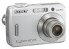 |
UPC - 027242692541
View all Sony DSC S500 manuals
Add to My Manuals
Save this manual to your list of manuals |
Page 6 highlights
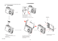
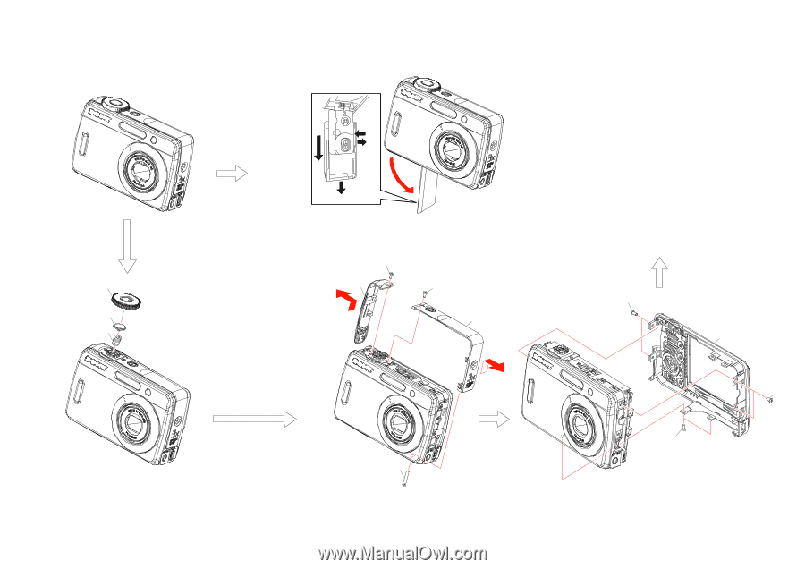
The following flow chart shows the disassembly procedure. 2-1. DISASSEMBLY 2. DISASSEMBLY 2 3 1 A Battery case lid removal 1 Pull out the battery case slowly until stop. 2 Put a nail into a slot. 3 Pull the battery case in the direction of arrow A. 1 1 2 1 2 4 3 1 Mode dial Take it off pulling over to upward. Push down adjusting rib width when attaching. 2 Shutter button 3 Shutter button spring DSC-S500 3 1 Two tapping screws (M1.7x3.5) silver 2 Middle cover assembly (right) 3 Tapping screw (M1.7x16) silver 4 Inner belt (left) 2-1 Front section (See page 2-2.) 1 2 1 1 1 Six tapping screws (M1.7x3.5) silver 2 Rear cover assembly
-
 1
1 -
 2
2 -
 3
3 -
 4
4 -
 5
5 -
 6
6 -
 7
7 -
 8
8 -
 9
9 -
 10
10 -
 11
11 -
 12
12 -
13
-
14
-
15
-
16
-
17
-
18
 |
 |
2-1
DSC-S500
1
2
3
1
1
1
1
2
3
2
4
1
1
Two tapping screws (M1.7x3.5) silver
2
Middle cover assembly (right)
3
Tapping screw (M1.7x16) silver
4
Inner belt (left)
Front section
(See page 2-2.)
1
Mode dial
2
Shutter button
3
Shutter button spring
1
Six tapping screws (M1.7x3.5) silver
2
Rear cover assembly
Take it off pulling over to upward.
Push down adjusting rib width when attaching.
Battery case lid removal
1
Pull out the battery case slowly until stop.
2
Put a nail into a slot.
3
Pull the battery case in the direction of arrow
A
.
A
1
2
3
2. DISASSEMBLY
2-1.
DISASSEMBLY
The following flow chart shows the disassembly procedure.