Sony DVP-S360 Operating Instructions (CD/DVD Component) - Page 8
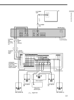
TV Hookups, CD/DVD player, Yellow, White L, Red R, To an AC outlet, Signal flow, To S VIDEO OUT - code
 |
View all Sony DVP-S360 manuals
Add to My Manuals
Save this manual to your list of manuals |
Page 8 highlights
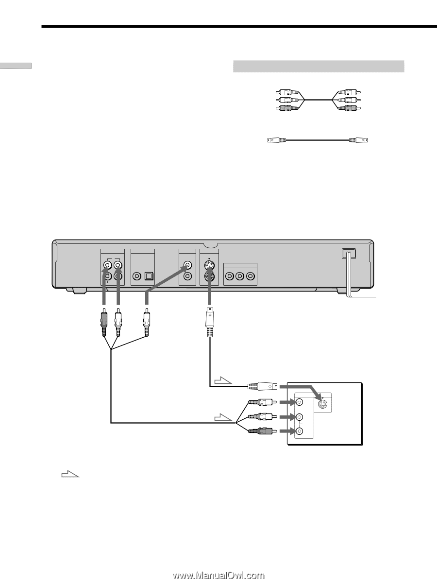
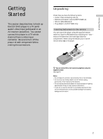
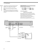
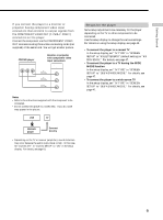
Getting Started TV Hookups This connection is for listening to the sound through TV speakers (L: left, R: right). Refer to the instructions supplied with the component to be connected. z You can enjoy surround sound using your TV's built-in speakers You can use 3D sound imaging to create virtual rear speakers from the sound of built-in TV speakers without using actual rear speakers (VES TV: Virtual Enhanced Surround TV). For details, see page 33. Required cords Audio/video connecting cord (supplied) (1) Yellow White (L) Red (R) S video cord (not supplied) (1) Yellow White (L) Red (R) When connecting the cords, be sure to match the color-coded cord to the appropriate jacks on the components: Yellow (video) to Yellow, Red (right) to Red and White (left) to White. Be sure to make connections firmly to avoid hum and noise. If your TV has an S video input connector, connect the component via the S VIDEO OUT connector using an S video cord (not supplied). You will get a better picture. Refer to the instructions supplied with the TV to be connected. CD/DVD player AUDIO OUT R L 1 DIGITAL OUT PCM/DTS/ DOLBY DIGITAL COAXIAL OPTICAL 2 VIDEO OUT S VIDEO OUT 1 1 2 2 COMPONENT VIDEO OUT Y PB/B-Y PR/R-Y To AUDIO OUT To VIDEO OUT To S VIDEO OUT To an AC outlet : Signal flow To S VIDEO input TV To video input To audio input INPUT VIDEO L AUDIO S VIDEO R 8
-
 1
1 -
2
-
 3
3 -
 4
4 -
 5
5 -
 6
6 -
 7
7 -
 8
8 -
 9
9 -
 10
10 -
 11
11 -
 12
12 -
 13
13 -
14
-
15
-
16
-
17
-
18
-
19
-
20
-
21
-
22
-
23
-
24
-
25
-
26
-
27
-
28
-
29
-
30
-
31
-
32
-
33
-
34
-
35
-
36
-
37
-
38
-
39
-
40
-
41
-
42
-
43
-
44
-
45
-
46
-
47
-
48
-
49
-
50
-
51
-
52
-
53
-
54
-
55
-
56
-
57
-
58
-
59
-
60
-
61
-
62
-
63
-
64
-
65
-
66
-
67
-
68
 |
 |