Sony DVP-S9000ES Operating Instructions - Page 75
AUDIO OUT R right/L left 1/2 connectors 10
 |
View all Sony DVP-S9000ES manuals
Add to My Manuals
Save this manual to your list of manuals |
Page 75 highlights
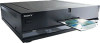
Additional Information Rear Panel AUDIO OUT R L 2 S-LINK CONTROL S IN DIGITAL OUT PCM/DTS/ DOLBY DIGITAL OPTICAL COAXIAL 1 2 2 Y 1 1 VIDEO S VIDEO OUT OUT COMPONENT VIDEO OUT PB PR SCAN SELECT SELECTABLE INTERLACE PROGRESSIVE 1 AUDIO OUT R (right)/L (left) 1/2 connectors (10, 12) Connect to the audio input connector on your TV or receiver (amplifier). 2 S-LINK/CONTROL S IN connector (10) Connect to the S-link (Control S) connector on an external component. 3 DIGITAL OUT OPTICAL connector (12, 15) Connect to an audio component using an optical digital connecting cord. Take off the cap. 4 DIGITAL OUT COAXIAL connector (12, 15) Connect to an audio component using a coaxial digital connecting cord. 5 VIDEO OUT 1/2 connectors (10) Connect to the video input connector on your TV or monitor. 6 S VIDEO OUT 1/2 connectors (10, 12, 15) Connect to the S video input connector on your TV or monitor. 7 COMPONENT VIDEO OUT (Y, PB, PR) connectors (11) Connects to a monitor or projector having component video input connectors (Y, PB, PR) that conform to output signals from the player. 8 SCAN SELECT switch (62) Select the component video signal format . • SELECTABLE: changes the format according to the setting made in "COMPONENT OUT" of the "CUSTOM SETUP" display. • INTERLACE: fixes to the format to interlace format. • PROGRESSIVE: fixes to the format to progressive format (480p). 75
-
 1
1 -
2
-
3
-
4
-
5
-
6
-
7
-
8
-
9
-
10
-
11
-
12
-
13
-
14
-
15
-
16
-
17
-
18
-
19
-
20
-
21
-
22
-
23
-
24
-
25
-
26
-
27
-
28
-
29
-
30
-
31
-
32
-
33
-
34
-
35
-
36
-
37
-
38
-
39
-
40
-
41
-
42
-
43
-
44
-
45
-
46
-
47
-
48
-
49
-
50
-
51
-
52
-
53
-
54
-
55
-
56
-
57
-
58
-
59
-
60
-
61
-
62
-
63
-
64
-
65
-
66
-
67
-
68
-
69
-
 70
70 -
 71
71 -
 72
72 -
 73
73 -
 74
74 -
 75
75 -
 76
76 -
 77
77 -
 78
78 -
 79
79 -
 80
80
 |
 |
