Sony DVPNS61 Service Manual - Page 3
DVP-NS37/NS45P/NS55P/NS61P/NS63P
 |
View all Sony DVPNS61 manuals
Add to My Manuals
Save this manual to your list of manuals |
Page 3 highlights
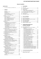
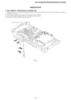
DVP-NS37/NS45P/NS55P/NS61P/NS63P TABLE OF CONTENTS SERVICE NOTE 1. Disc Removal Procedure (at POWER OFF 5 1. GENERAL WARNING 1-1 Notes About the Discs 1-1 Precautions 1-1 About This Manual 1-1 This Player Can Play the Following Discs 1-1 Index to Parts and Controls 1-2 Guide to the Control Menu Display 1-3 Hookups 1-3 Hooking Up the Player 1-3 Step 1: Unpacking 1-3 Step 2: Inserting Batteries into the Remote 1-3 Step 3: Connecting the Video Cords 1-4 Step 4: Connecting the Audio Cords 1-4 Step 5: Connecting the Mains Lead 1-5 Step 6: Quick Setup 1-5 Playing Discs 1-5 Playing Discs 1-5 Resuming Playback from the Point Where You Stopped the Disc (Multi-disc Resume 1-6 Using the DVD's Menu 1-6 Selecting "ORIGINAL" or "PLAY LIST" on a DVD-RW/DVD-R 1-6 Playing VIDEO CD's With PBC Functions (PBC Playback 1-6 Various Play Mode Functions (Programme Play, Shuffle Play, Repeat Play, A-B Repeat Play 1-7 Searching for a Scene 1-8 Searching for a Particular Point on a Disc (Search, Scan, Slow-motion Play, Freeze Frame 1-8 Searching for a Title/Chapter/Track/Scene, etc 1-8 Searching by Scene (PICTURE NAVIGATION 1-8 Viewing Information About the Disc 1-9 Checking the Playing Time and Remaining Time 1-9 Sound Adjustments 1-9 Changing the Sound 1-9 TV Virtual Surround Settings (TVS 1-10 Enjoying Movies 1-10 Changing the Angles 1-10 Displaying the Subtitles 1-10 Adjusting the Playback Picture (CUSTOM PICTURE MODE 1-11 Sharpening the Picture (SHARPNESS 1-11 Enjoying MP3 Audio and JPEG Images 1-11 About MP3 Audio Tracks and JPEG Image Files 1-11 Playing MP3 Audio Tracks and JPEG Image Files ......... 1-12 Enjoying JPEG Images as a Slide Show 1-12 Enjoying DivX Videos 1-13 About DivX Video Files 1-13 Playing DivX Video Files 1-13 Using Various Additional Functions 1-14 Locking Discs (CUSTOM PARENTAL CONTROL, PARENTAL CONTROL 1-14 Controlling Your TV with the Supplied Remote 1-15 Settings and Adjustments 1-16 Using the Setup Display 1-16 Setting the Display or Sound Track Language (LANGUAGE SETUP 1-16 Settings for the Display (SCREEN SETUP 1-16 Custom Settings (CUSTOM SETUP 1-16 Settings for the Sound (AUDIO SETUP 1-16 Additional Information 1-17 Troubleshooting 1-17 Self-diagnosis Function (When letters/ numbers appear in the display 1-18 Glossary 1-18 Specifications 1-18 2. DISASSEMBLY 2-1. Upper Case 2-1 2-2. Front Panel Assembly 2-1 2-3. Loading Assembly 2-2 2-4. Optical Pick-Up (Device, Optical KHM-313CAA/C2RP 2-3 2-5. Rear Panel, MV Board and IF Board 2-4 2-5-1. Rear Panel, MV-51 and IF-144/IF-145 Boards 2-4 2-5-2. Rear Panel, MV-50 and IF-144 Boards 2-5 2-6. Switching Regulator 2-5 2-7. Interval Views 2-6 2-8. Circuit Boards Location 2-7 3. BLOCK DIAGRAMS 3-1. Overall Block Diagram 3-1 3-2. Power Line Block Diagram 3-3 3-3. System Control/Signal Processor Block Diagram 3-5 3-4. RF/Servo Block Diagram 3-7 3-5. Video (1) Block Diagram 3-9 3-6. Video (2) Block Diagram 3-11 3-7. Audio Block Diagram 3-13 3-8. Interface Control Block Diagram 3-15 4. PRINTED WIRING BOARDS AND SCHEMATIC DIAGRAMS 4-1. Frame Schematic Diagram 4-1 4-2. Printed Wiring Boards and Schematic Diagrams 4-3 • Waveforms MV-50 Board (DVP-NS36/NS37 4-4 MV-51 Board (DVP-NS45P/55P/61P/63P 4-5 • IF-144 Printed Wiring Board 4-7 • IF-144 (Interface) Schematic Diagram 4-9 • IF-145 Printed Wiring Board 4-11 • IF-145 (Interface) Schematic Diagram 4-13 • MS-203 Printed Wiring Board 4-15 • MS-203 (Loading Motor) Schematic Diagram 4-16 • MV-50 Printed Wiring Board 4-17 • MV-50 (CPU, Servo-DSP, AVDEC) Schematic Diagram 4-19 • MV-50 (Drive) Schematic Diagram 4-21 • MV-50 (Video Euro) Schematic Diagram 4-23 • MV-50 (Audio) Schematic Diagram 4-25 • MV-50 (Power) Schematic Diagram 4-27 • MV-51 Printed Wiring Board 4-29 • MV-51 (CPU, Servo-DSP, AVDEC) Schematic Diagram 4-31 • MV-51 (Drive) Schematic Diagram 4-33 • MV-51 (Video) Schematic Diagram 4-35 • MV-51 (Audio) Schematic Diagram 4-37 • MV-51 (Power) Schematic Diagram 4-39 • SW-468 Printed Wiring Board 4-41 • SW-468 (Switch) Schematic Diagram 4-42 • SW-475 Printed Wiring Board 4-43 • SW-475 (Switch) Schematic Diagram 4-44 • Power Block (SRV1872WW) Printed Wiring Board .... 4-45 • Power Block (SRV1872WW) Schematic Diagram ..... 4-47 • Power Block (SRV1873UC) Printed Wiring Board ..... 4-49 • Power Block (SRV1873UC) Schematic Diagram ....... 4-51 5. IC PIN FUNCTION DESCRIPTION 5-1. System Control Pin Function (MV-50/51 Boards IC101 5-1 - 3 -
-
 1
1 -
 2
2 -
 3
3 -
 4
4 -
 5
5 -
 6
6 -
 7
7 -
 8
8 -
 9
9 -
10
-
11
-
12
-
13
-
14
-
15
-
16
-
17
-
18
-
19
-
20
-
21
-
22
-
23
-
24
-
25
-
26
-
27
-
28
-
29
-
30
-
31
-
32
-
33
-
34
-
35
-
36
-
37
-
38
-
39
-
40
-
41
-
42
-
43
-
44
-
45
-
46
-
47
-
48
-
49
-
50
-
51
-
52
-
53
-
54
-
55
-
56
-
57
-
58
-
59
-
60
-
61
-
62
-
63
-
64
-
65
-
66
-
67
-
68
-
69
-
70
-
71
-
72
-
73
-
74
-
75
-
76
-
77
-
78
-
79
-
80
-
81
-
82
-
83
-
84
-
85
-
86
-
87
-
88
-
89
-
90
-
91
-
92
-
93
-
94
-
95
-
96
 |
 |
