Sony FCBEX490DP User Manual (FCB-490D_Technical_Manual) - Page 18
Sending Alarms, Setting Commands, Frame Number bit0: Frame0, bit1: Frame1, bit2
 |
View all Sony FCBEX490DP manuals
Add to My Manuals
Save this manual to your list of manuals |
Page 18 highlights
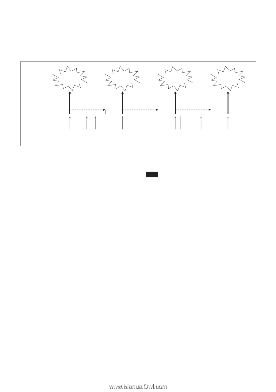
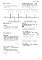
Sending Alarms • When motion is detected, the Alarm Replay command is issued via the serial command (VISCA) communication line. Basic Functions • When multiple motions are detected or motion is detected in another frame within the set interval following the original time the alarm was issued, another alarm command is not issued. • When motion is detected after the interval time elapsed, the alarm is issued again. Alarm issue Alarm issue Alarm issue Alarm issue Alarm interval Interval Interval Interval Motion is Motion is Motion is Motion is detected detected detected detected in frame 1. in frame 1. in frame 1. in frame 1. Motion is Motion is Motion is Motion is detected detected detected detected in frame 1. in frame 2. in frame 3. in frame 3. Setting Commands • MD On/Off The Display mode is selected by the Function Set command and frames are set by the Frame Set command. By sending an MD On command, the frame is displayed when motion is detected in the set frame. The Alarm Reply command is set via the serial command (VISCA) communication line. 8x 01 04 1B 02 FF --- On 8x 01 04 1B 03 FF --- Off • Function Set The Display mode function has two modes. One is the Frame Mode, in which the detected frame is displayed on the screen, and the other is the Block Mode in which the block where the motion is detected is displayed from among the set of 12 (horizontally) × 8 (vertically) blocks. The Frame Mode is normally used. For examination and verification when the camera is installed, display blocks using the Block Mode. In the Block Mode, the Alarm Reply command is not sent. 8x 01 04 1C 0m 0n 0p 0q 0r 0s FF m: Display Mode on/off (bit0: Frame, bit1: Block) n: Detection Frame set on/off (bit0:Frame0, bit1:Frame1, bit2:Frame2, bit3:Frame3) -- (0 to F) pq: Threshold -- (00 to FF) rs: Interval time set -- (00 to FF) (When pq and rs are 0, the command is received, but the setting is disabled.) • Frame Set You can set up to four frames by assigning the starting and terminating points. Note Set a terminating point higher vertically and horizontally than the starting point. If you set the wrong value, the command yields an error. 8x 01 04 1D 0m 0p 0q 0r 0s FF m: Select Detection Frame (0: Frame0, 1: Frame1, 2: Frame2, 3: Frame3) -- (0, 1, 2, 3) p: Frame set Start Horizontal Position -- (00 to 0B) q: Frame set Start Vertical Position -- (00 to 07) r: Frame set End Horizontal Position -- (01 to 0C) s: Frame set End Vertical Position -- (01 to 08) • Alarm Reply When motion is detected in the set frame, the camera issues this command. This command includes the information on the number of the detected frame. y0 07 04 1B 0p FF p: Frame Number (bit0: Frame0, bit1: Frame1, bit2: Frame2, bit3: Frame3) 18
-
 1
1 -
2
-
3
-
4
-
5
-
6
-
7
-
8
-
9
-
10
-
11
-
12
-
 13
13 -
 14
14 -
 15
15 -
 16
16 -
 17
17 -
 18
18 -
 19
19 -
 20
20 -
 21
21 -
 22
22 -
 23
23 -
24
-
25
-
26
-
27
-
28
-
29
-
30
-
31
-
32
-
33
-
34
-
35
-
36
-
37
-
38
-
39
-
40
-
41
-
42
-
43
-
44
-
45
-
46
-
47
-
48
-
49
-
50
-
51
-
52
 |
 |