Sony FCBEX490DP User Manual (FCB-490D_Technical_Manual) - Page 20
Key Switch Circuitry
 |
View all Sony FCBEX490DP manuals
Add to My Manuals
Save this manual to your list of manuals |
Page 20 highlights
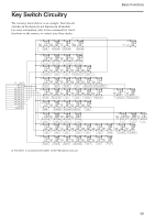
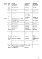
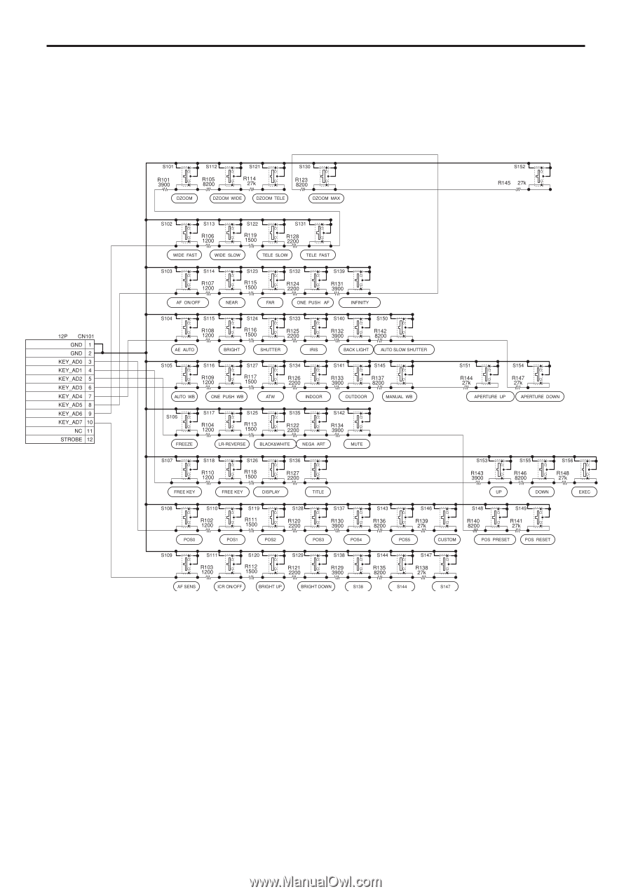
Key Switch Circuitry The circuitry shown below is an example. Note that all switches in the figure do not function in all models. For more information, refer to the command list, check functions on the camera, or contact your Sony dealer. Basic Functions a) a) The CN101 is connected to the CN501 on the FCB camera main unit. 20
-
 1
1 -
2
-
3
-
4
-
5
-
6
-
7
-
8
-
9
-
10
-
11
-
12
-
13
-
14
-
 15
15 -
 16
16 -
 17
17 -
 18
18 -
 19
19 -
 20
20 -
 21
21 -
 22
22 -
 23
23 -
 24
24 -
 25
25 -
26
-
27
-
28
-
29
-
30
-
31
-
32
-
33
-
34
-
35
-
36
-
37
-
38
-
39
-
40
-
41
-
42
-
43
-
44
-
45
-
46
-
47
-
48
-
49
-
50
-
51
-
52
 |
 |
20
Basic Functions
Key Switch Circuitry
The circuitry shown below is an example. Note that all
switches in the figure do not function in all models.
For more information, refer to the command list, check
functions on the camera, or contact your Sony dealer.
a)
a) The CN101 is connected to the CN501 on the FCB camera main unit.