Sony ICF-SW7600GR Service Manual - Page 6
Disassembly, Cabinet (rear), Electrical Adjustments - antenna jack
 |
UPC - 027242580084
View all Sony ICF-SW7600GR manuals
Add to My Manuals
Save this manual to your list of manuals |
Page 6 highlights
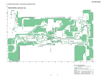
ICF-SW7600GR SECTION 2 DISASSEMBLY Note : Follow the disassembly procedure in the numerical order given. 2-1. CABINET (REAR) 2 Two screws (+BTP 3 × 25) 1 Three screws (+BTP 3 × 25) 4 Cabinet (rear) 3 Four claws SECTION 3 ELECTRICAL ADJUSTMENTS • AM Section AM RF signal generator Put the lead-wire antenna close to the set. 30% amplitude modulation by 400Hz signal output level: as low as possible • FM Section FM RF signal generator FM RF IN set 22.5kHz frequency deviation by 400Hz signal output level: as low as possible 16 Ω level meter set i headphones jack (J202) (1) AM / FM VCO Check and Adjustment Setting: ATT switch : OFF TONE switch : MUSIC AM MODE switch : NORM Procedure: 1. Connect digital voltmeter to the TP VT. 2. Tune the set to AM 150kHz. 3. Confirm that the reading on the digital voltmeter becomes in more than 2.2V. 4. Tune the set to AM 29999kHz. 5. Confirm that the reading on the digital voltmeter becomes in less than 13V. 6. Tune the set to FM 108.00MHz. 7. Confirm that the reading on the digital voltmeter becomes in less than 13V. 8. IF the value is more than 13V, adjust T202 so that the reading on the digital voltmeter becomes in 12.5V. Adjustment Location: MAIN board (See page 8) (2) 1st IF Adjustment Setting : ATT switch : OFF TONE switch : MUSIC AM MODE switch : NORM Procedure: 1. Set the frequencies of the AM RF signal generator and the frequency display of the set to AM 150kHz. 2. Adjust T104 and T105 so that the reading on level meter becomes in maximum. Adjustment Location: MAIN board (See page 8) 6
-
 1
1 -
 2
2 -
 3
3 -
 4
4 -
 5
5 -
 6
6 -
 7
7 -
 8
8 -
 9
9 -
 10
10 -
 11
11 -
 12
12 -
13
-
14
-
15
-
16
-
17
-
18
-
19
-
20
-
21
-
22
-
23
-
24
-
25
-
26
 |
 |
