Sony JH1 Product Manual (JH1 / JH3 manual) - Page 10
Example for the J-H3
 |
View all Sony JH1 manuals
Add to My Manuals
Save this manual to your list of manuals |
Page 10 highlights
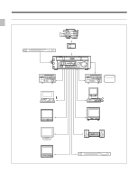
1-2 Sample System Configuration Example for the J-H3 HDCAM camcorder Chapter 1 Overview Reference video signal generator EXT SYNC Digital cassette RS-422A J-H3 SD VTR SD SDI Computer DV1) HD SDI HD VTR or A/V server system JZ-1 RS-232C Computer D3 Monitor with HD D3 input connector Analog composite SD video monitor MONITOR Monitor for computer Analog audio Audio monitor Analog component TC OUTPUT Monitor with Y/Pb/Pr input connectors Time code reader ...1) When an HKJ-101 i.LINK Interface Board is installed. 1-4 Chapter 1 Overview
-
 1
1 -
2
-
3
-
4
-
 5
5 -
 6
6 -
 7
7 -
 8
8 -
 9
9 -
 10
10 -
 11
11 -
 12
12 -
 13
13 -
 14
14 -
 15
15 -
16
-
17
-
18
-
19
-
20
-
21
-
22
-
23
-
24
-
25
-
26
-
27
-
28
-
29
-
30
-
31
-
32
-
33
-
34
-
35
-
36
-
37
-
38
-
39
-
40
-
41
-
42
-
43
-
44
-
45
-
46
-
47
-
48
-
49
-
50
-
51
-
52
-
53
 |
 |

Chapter 1
Overview
1-4
Chapter 1
Overview
1-2
Sample System Configuration
1) When an HKJ-101 i.LINK Interface Board is installed.
..........................................................................................................................................................................................................
Analog
audio
RS-232C
HDCAM camcorder
JZ-1
Monitor with Y/Pb/Pr
input connectors
Analog
composite
Digital cassette
J-H3
SD SDI
HD SDI
Computer
Computer
SD video monitor
Audio monitor
Monitor with HD D3 input connector
Monitor for computer
Time code reader
Reference video signal generator
HD VTR or A/V server system
SD VTR
EXT SYNC
DV
1)
TC
OUTPUT
D3
Analog
component
RS-422A
MONITOR
Example for the J-H3