Sony JH1 Product Manual (JH1 / JH3 manual) - Page 18
Connector Panel
 |
View all Sony JH1 manuals
Add to My Manuals
Save this manual to your list of manuals |
Page 18 highlights
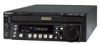
2-2 Connector Panel 1 TC OUTPUT connector 2 AC IN connector Chapter 2 Location and Function of Parts 7 EXT SYNC connectors 5 VIDEO OUTPUT connectors 6 AUDIO MONITOR OUTPUT connectors This illustration shows the J-H3 equipped with an HKJ-101 i.LINK Interface Board. 3 REMOTE IN connector 4 RS-232C connector 1 TC OUTPUT (time code output) connector (BNC type ×1) (J-H3 only): Outputs the playback time code. 2 AC IN connector Connects to an AC outlet using the power cord (not supplied). Notes • Place the unit near the AC outlet for easier reach of the breaker. • Make sure to perform a ground connection for the unit before you plug the unit into the wall outlet. If you disconnect the grounding, unplug the unit from the wall outlet first. 3 REMOTE IN (9P) (remote control signal input) connector (D-sub 9-pin, female) (J-H3 only): Connects to a BVE series editor or other VTR using a 9-pin remote control cable (not supplied) to externally control the unit. 4 RS-232C (RS-232C serial interface) connector (D-sub 9-pin, male) Exchanges the RS-232C serial remote control signal and the VTR status signal with external devices such as a computer installed JZ-1. 5 VIDEO OUTPUT connectors SD (D CONV.) (SD output) connectors COMPOSITE (SUPER) (analog composite video output) connector (Phono jack ×1): Outputs an analog composite video signal. COMPOSITE (SUPER) (analog composite video output) connector (BNC type ×1): Outputs an analog composite video signal. SDI (SUPER) (serial digital interface output) connector (BNC type ×1) (J-H3 only): Outputs video/audio signals in D1 format. 2-7 Chapter 2 Location and Function of Parts
-
 1
1 -
2
-
3
-
4
-
5
-
6
-
7
-
8
-
9
-
10
-
11
-
12
-
 13
13 -
 14
14 -
 15
15 -
 16
16 -
 17
17 -
 18
18 -
 19
19 -
 20
20 -
 21
21 -
 22
22 -
 23
23 -
24
-
25
-
26
-
27
-
28
-
29
-
30
-
31
-
32
-
33
-
34
-
35
-
36
-
37
-
38
-
39
-
40
-
41
-
42
-
43
-
44
-
45
-
46
-
47
-
48
-
49
-
50
-
51
-
52
-
53
 |
 |
